

Tool for cutting joint of masonry wall
- Summary
- Abstract
- Description
- Claims
- Application Information
AI Technical Summary
Benefits of technology
Problems solved by technology
Method used
Image

Examples
Embodiment Construction
[0034]The present disclosure are described hereafter in detail with reference to the embodiments proposed in the accompanying drawings, but the proposed embodiments are provided as examples for clear understanding of the present disclosure and the present disclosure is not limited thereto.
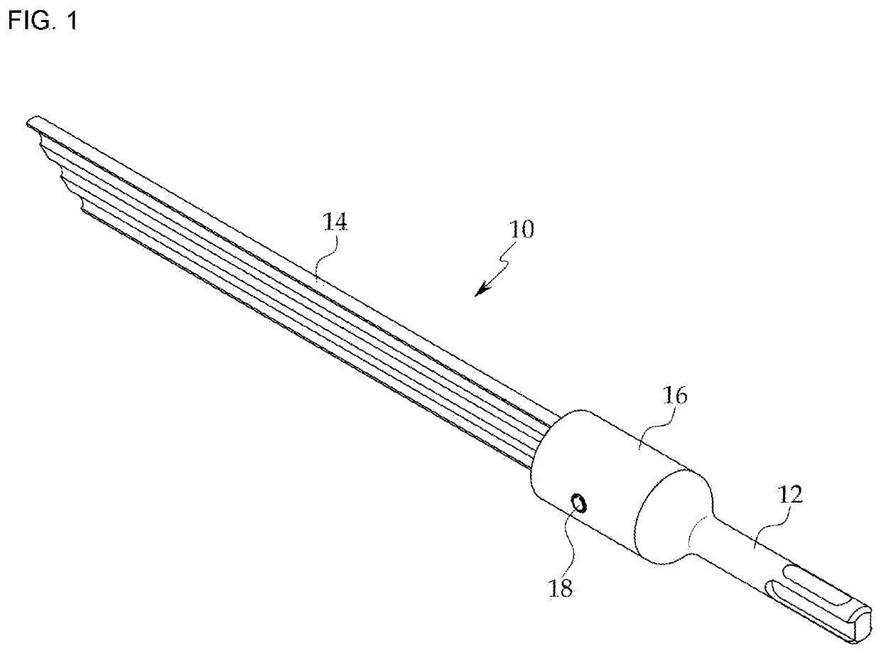
[0035]A tool 10 for cutting joints of a masonry wall of the present disclosure is, as shown in FIG. 5, a tool that is connected to an electric motor 100 in use to cut (dig) joints 5a formed in a masonry wall by a predetermined depth. The tool 10 for cutting joints of a masonry wall may be used at a predetermined angle.
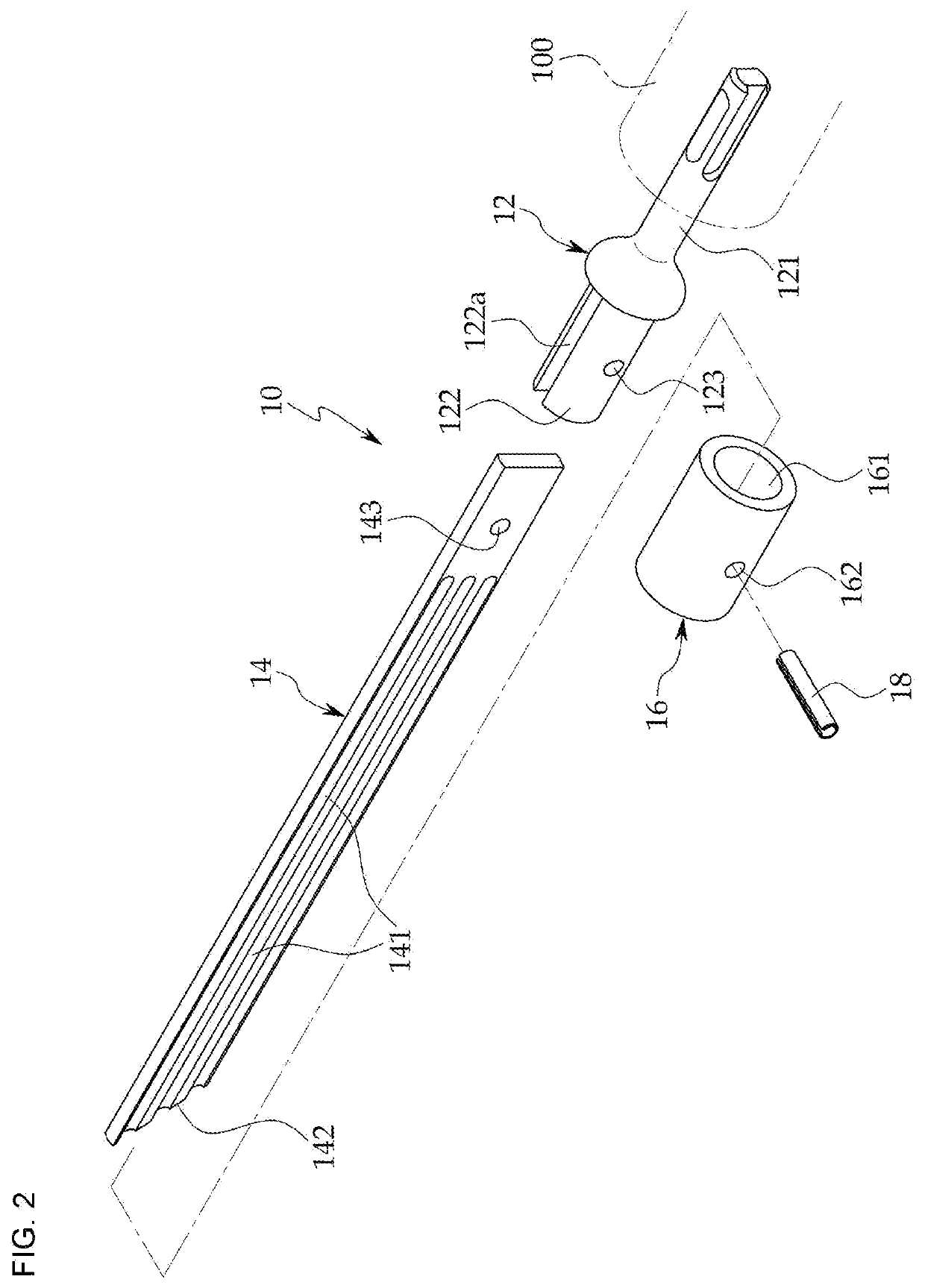
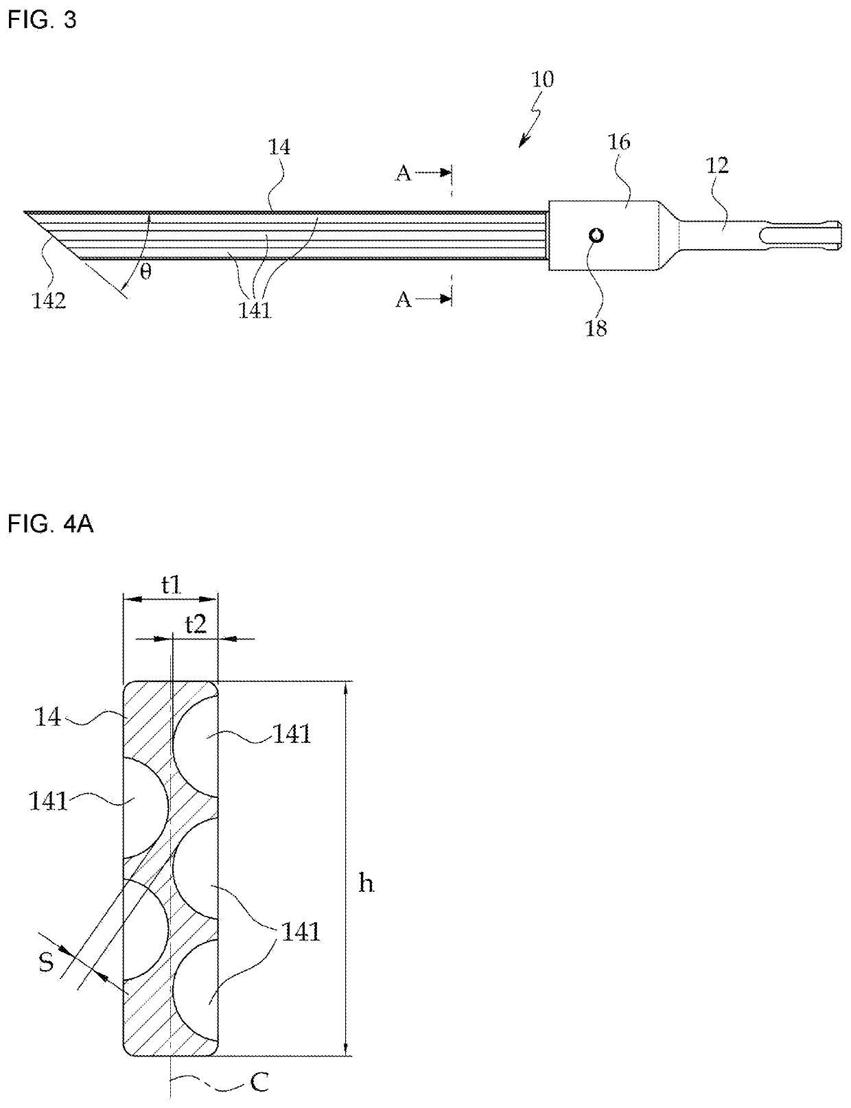
[0036]The tool 10 for cutting joints of a masonry wall according to the first embodiment is configured to be manufactured in an assembly type, as shown in FIGS. 1 to 4D. As shown in FIGS. 1 to 4D, the tool 10 for cutting joints of a masonry wall includes: a cutter shank 12 that is connected to the output end of an electric motor 100 through a chuck to receive vibration; a joint cutter...
PUM
 Abstract
Description
Claims
Application Information