Method for processing difficult-to-cut cast iron

Active Publication Date: 2012-08-30
SUMITOMO ELECTRIC HARDMETAL CORP
View PDF8 Cites 0 Cited by
  • Summary
  • Abstract
  • Description
  • Claims
  • Application Information

AI Technical Summary

Benefits of technology

[0021]As clearly seen from the description above, the method for processing a difficult-to-cut cast iron of the present inventio

Problems solved by technology

Even if the cutting insert formed of a CBN sintered body is used, however, the cutting speed increased to 400 m/min or more will cause a rapid progression of wear and/or chipping of the cutting insert, resulting in a problem that cutting at a higher speed is difficult to achieve.
When the difficult-to-cut cast iron is cut, however, the temperature of the edge of the cutting insert is prone to increase while cutting is done.
If a cutting insert is employed that is formed

Method used


Image

  • Method for processing difficult-to-cut cast iron
  • Method for processing difficult-to-cut cast iron

Examples


Example

Example 1

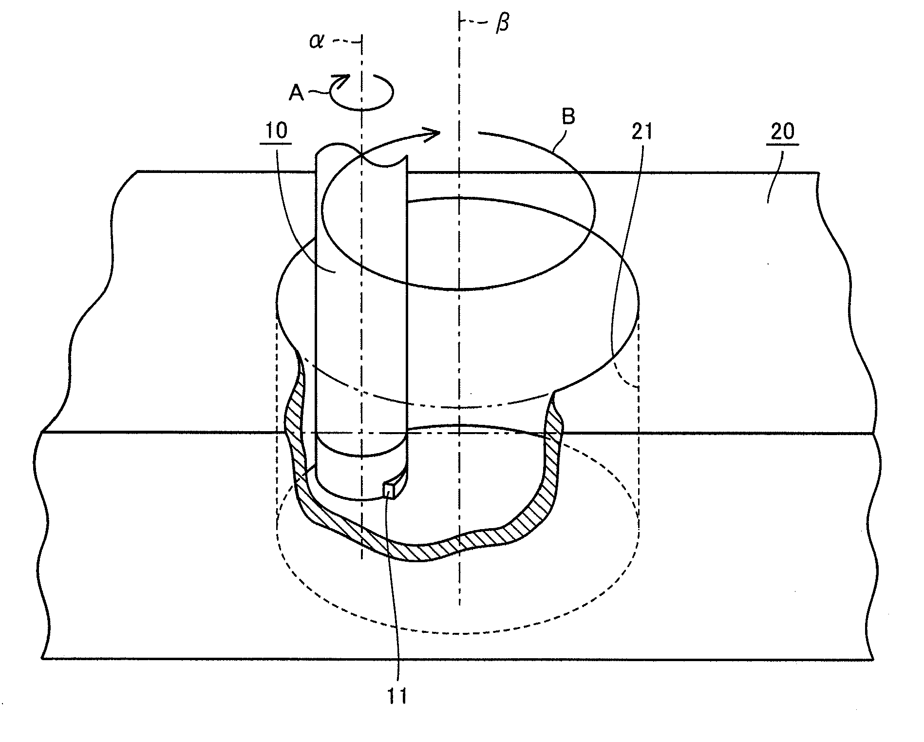
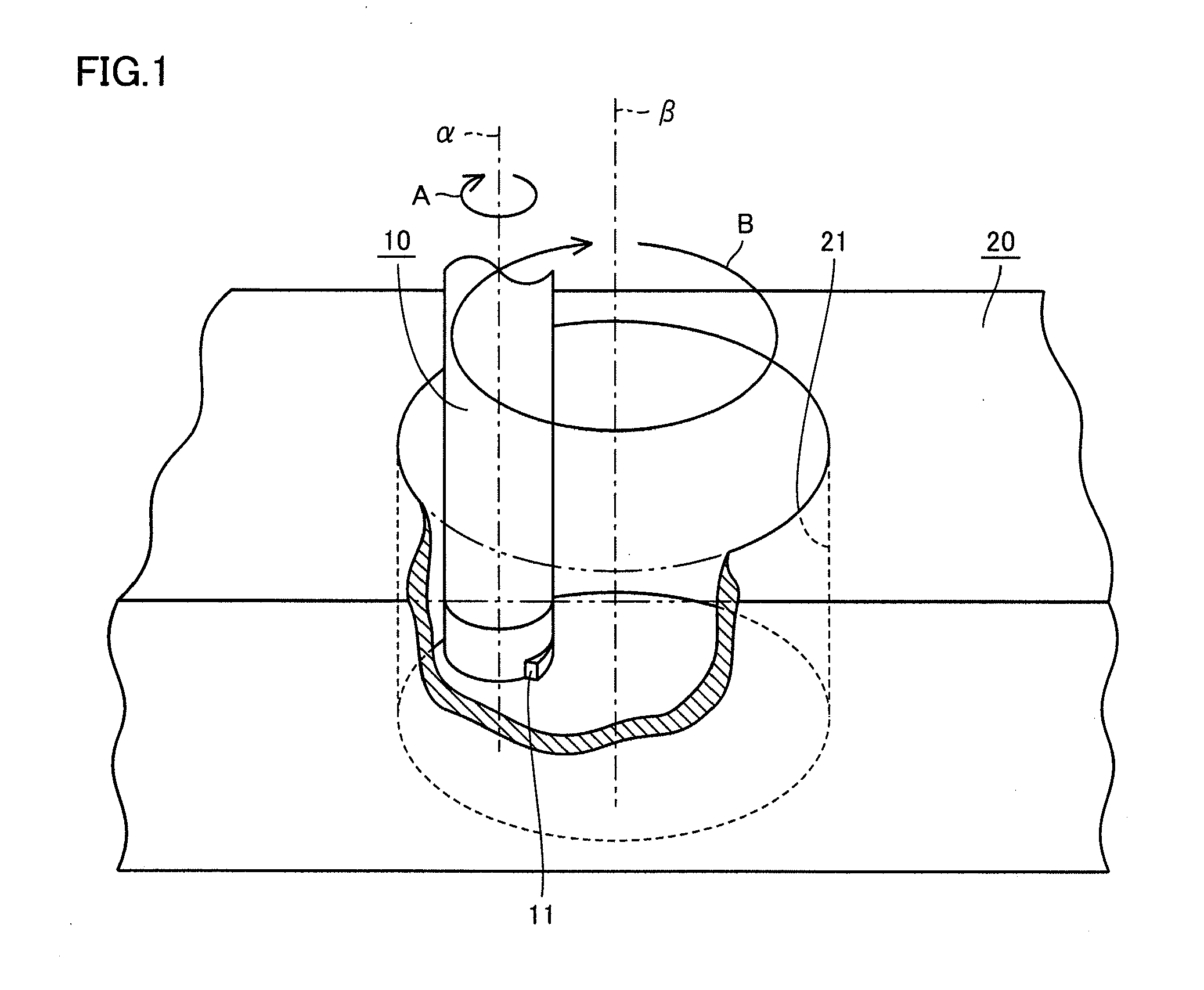
[0032]In the following, Example 1 will be described. An experiment was conducted in which a cutting insert formed of a CBN sintered body was used to perform inner-periphery contouring and continuous inner-periphery cutting on a workpiece made of FCD450 which is a difficult-to-cut cast iron, and examine influences, on the amount of wear of the cutting insert, of the processing method, the CBN content of the cutting insert, and the thermal conductivity of the cutting insert. Table 1 shows conditions under which inner-periphery contouring was performed and Table 2 shows conditions under which continuous inner-periphery cutting was performed. Further, Table 3 shows the CBN content and the thermal conductivity of the cutting insert as well as the amount of wear of the flank face of the cutting insert at the time when the volume of a swarf removed from the workpiece by cutting had become 50 cm3. Here, as the cutting insert, Model No. CNGA120408 was employed. Further, a binder whi...

Example

[0033]Referring to Table 3, from a comparison between Example B of the present invention and Comparative Example A falling out of the scope of the present invention in which the same cutting insert as that of Example B was used, it is seen that the amount of wear of the flank face in Example B is remarkably smaller than the amount of wear of the flank face in Comparative Example A, while respective processing efficiencies are identical to each other. The reason for this is assumed to be as follows. Regarding Example B in which contouring is employed, the contact time for which the edge of the cutting insert contacts the workpiece is a short time of a few microseconds or less, so that the cutting edge is cooled while the insert makes noncontact rotation and revolution before the temperature of the edge increases to exceed its limit. Therefore, the wear may be suppressed as compared with Comparative Example A in which the edge continuously contacts the workpiece. It has been confirmed...

Example

[0034]From a comparison between Examples A to C and Comparative Example B that all employ the contouring, it is also seen that the flank face of Comparative Example B wears to a greater extent. The reason for this is considered to be as follows. As for Comparative Example B, the thermal conductivity is less than 100 W / (mK), and therefore the edge temperature is prone to increase. In addition, since the CBN content is less than 85% by volume, the material strength is low and mechanical wear predominantly develops. In view of the above, it has been confirmed that, under the condition that contouring is used for cutting of a difficult-to-cut cast iron with a cutting insert formed of a CBN sintered body, the content of CBN of the cutting insert can be set to 85% by volume or more and the thermal conductivity can be set to 100 W / (mK) or more to thereby suppress wear of the cutting insert to a sufficient extent.

[0035]Further, as for Examples A to C, a higher CBN content and a higher therm...


PUM

PropertyMeasurementUnit
Timeaaaaaaaaaa
Timeaaaaaaaaaa
Poweraaaaaaaaaa

Abstract

In a pilot hole of a workpiece made of a difficult-to-cut cast iron, a cutting tool having a leading end to which a cutting insert is attached is inserted to cut the surface of the wall of the pilot hole. At this time, the cutting tool rotates about an axis (α) and also revolves about another axis (β), so that contouring is performed on the workpiece by the tool. The cutting insert is formed of a sintered body having a CBN content of not less than 85% by volume, and the cutting insert has a thermal conductivity of not less than 100 W/(mK).

Description

TECHNICAL FIELD[0001]The present invention relates to a method for processing a difficult-to-cut cast iron. More specifically, the invention relates to a method for processing a difficult-to-cut cast iron when cutting the difficult-to-cut cast iron using a cutting insert containing CBN (Cubic Boron Nitride), by which extension of the life of the cutting insert and improvement of the cutting speed can both be achieved.BACKGROUND ART[0002]For cutting cast irons except for the FC material, namely materials such as the FCD, FCV, CGI, and ADI materials that are difficult-to-cut cast irons, generally low-speed processing (cutting speed V is 200 m / min or lower) is employed for which an insert coated with cemented carbide is used. In some cases, with the aim of improving the cutting speed, a cutting insert formed of a sintered body containing CBN (CBN sintered body) may be employed to cut a difficult-to-cut cast iron. Even if the cutting insert formed of a CBN sintered body is used, however...

Claims


Application Information

Patent Timeline
IPC IPC(8): B23C3/00
CPCB23C3/02Y10T409/303808B23C2226/125B23C2222/14Y10T407/26B23C5/20
Inventor OKAMURA, KATSUMIKUKINO, SATORUFUKAYA, TOMOHIRO
Owner SUMITOMO ELECTRIC HARDMETAL CORP
Why Eureka
Try Eureka