Coated insert

a cemented carbide and metal cutting technology, applied in the direction of superimposed coating process, other chemical processes, instruments, etc., can solve the problems of tool wear by different mechanisms, fracturing of cutting edge, abrasion and chemical wear,

Active Publication Date: 2008-07-08
SANDVIK INTELLECTUAL PROPERTY AB +1
View PDF23 Cites 33 Cited by
  • Summary
  • Abstract
  • Description
  • Claims
  • Application Information

AI Technical Summary

Benefits of technology

[0011]It is a further object of the present invention to avoid or alleviate problems associated with prior art tool products and to provide a high performance tool for high cutting speeds.
[0012]It is a still further object of the present invention to provide a tool with excellent cutting performance in demanding stainless steel turning operations.

Problems solved by technology

When cemented carbide cutting tools are used in the machining of steels, the tool is worn by different mechanisms such as abrasive and chemical wear, chipping and fracturing of the cutting edge.
A high temperature within the edge region in combination with high cutting forces result in an increase of the creep deformation within the affected surface region of the substrate and the cutting edge deforms plastically.
The cutting of stainless steel is considered to be a particularly difficult machining operation since in addition to the above mentioned wear mechanisms, adhesive wear and plastic deformation are also prominent factors.
Adhesive wear occurs when smearing materials like stainless steels during the cutting operation continuously adhere to and tear off material from the cutting edge.
A short tool life is therefore very frequent when machining stainless steels.
Furthermore, austenitic and so called duplex stainless steels exhibit strong deformation hardening which results in high contact forces, e.g., between the chip and the surface of the tool.
When cutting such workpiece materials at high cutting speeds, considerable thermal energy is transferred to the cutting edge and, in combination with the high cutting forces, the tool edge may partly or entirely deform plastically.
Deformation of the edge, which is mainly controlled by the properties of the surface region of the substrate, results in larger cutting forces and thus a reduced tool life.
Damages of this kind, normally denoted chip hammering and chip jamming, may partly or wholly be avoided by selecting a proper microgeometry of the active edge surfaces of the insert but in several cases this possibility is not enough.
However, regarding the cemented carbide substrate, the combination of a high nominal content of binder phase and a thick γ-phase depleted surface zone followed by a zone characterized by a high concentration peak of γ-phase, all in relative terms, does not favor the resistance against plastic deformation.
This will result in rapid wear and short tool life for machining austenitic and duplex stainless steels at high cutting speeds.

Method used


Image

  • Coated insert
  • Coated insert
  • Coated insert

Examples


example 1

[0089]Inserts from A1, A2 and E were tested in a turning operation.[0090]Operation: External axial and facing of bar[0091]Work piece material: Austenitic stainless steel, AISI304L

[0092]

Cutting Speed:270m / minFeed rate:0.3mm / revDepth of cut:2mmInsert style:CNMG 120408-MMResults:Tool lifeInsert A1: (invention)9minInsert A2: (invention)9minInsert E: (prior art)5min

[0093]Comment: Tool life criterion was maximum flank wear 0.3 mm of the cutting edge line. The wear develops irregularly due to local plastic deformation. This example shows the improvement in plastic deformation resistance for the inserts of the invention.

example 2

[0094]Inserts from B1, B2 and E were tested in a turning operation.[0095]Operation: Axial and facing operation of bar[0096]Work piece material: Austenitic stainless steel, AISI304L

[0097]

Cutting speed:290m / minFeed rate:0.2mm / revDepth of cut:2mmInsert style:CNMG 120408-MMResults:Tool lifeInsert B1: (invention)17minInsert B2: (invention)17minInsert E: (prior art)8min

[0098]Comment: Tool life criterion was maximum flank wear 0.3 mm of the cutting edge line. The wear develops irregularly due to local plastic deformation. This example shows the improvement in plastic deformation resistance for the inserts of the invention.

example 3

[0099]Inserts from B1, D and E were tested in a turning operation.[0100]Operation: Axial and facing against shoulder[0101]Work piece material: Austenitic stainless steel, AISI304L

[0102]

Cutting speed:270m / minFeed rate:0.3mm / revDepth of cut:2mmInsert styles:CNMG 120408-MMResults:Edge damageInsert B1: (invention)0.2mm / minInsert D: (prior art)0.9mm / minInsert E: (prior art)0.2mm / min

[0103]Comment: The test is focused on induced damage of the edge outside the direct area of contact between the tool and the workpiece, normally denoted chip hammering and chip jamming. The resistance of such damages is directly related to the edge toughness.

[0104]The insert of the invention shows improvements in these respects. The edge toughness is increased (inserts B1 and D) or maintained (inserts B1 and E) while the plastic deformation resistance is increased (example 2).


PUM

PropertyMeasurementUnit
grain sizeaaaaaaaaaa
total thicknessaaaaaaaaaa

Abstract

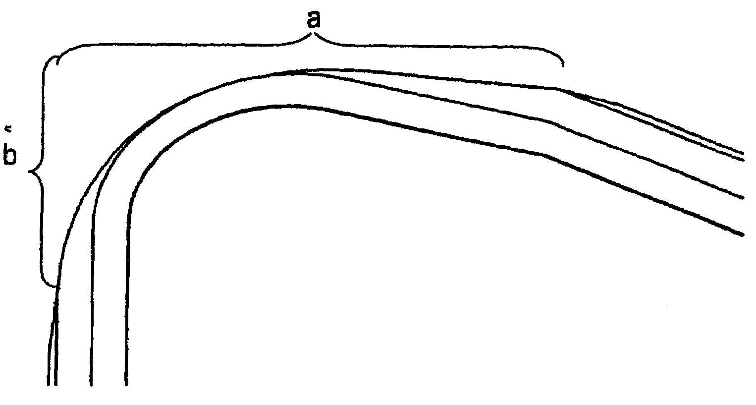
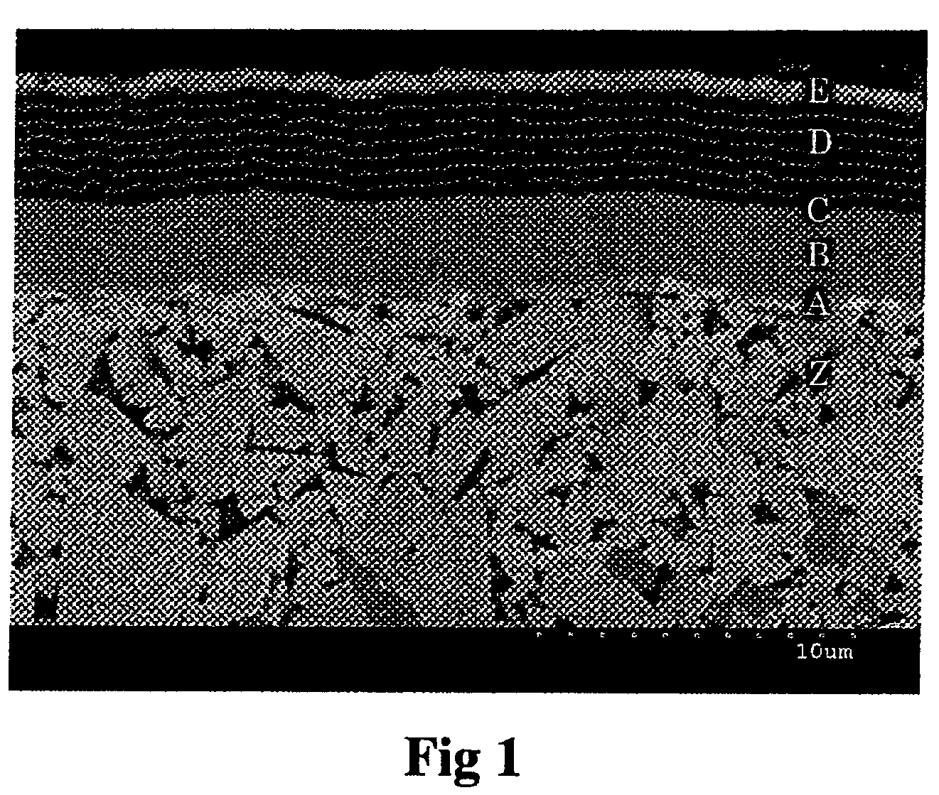
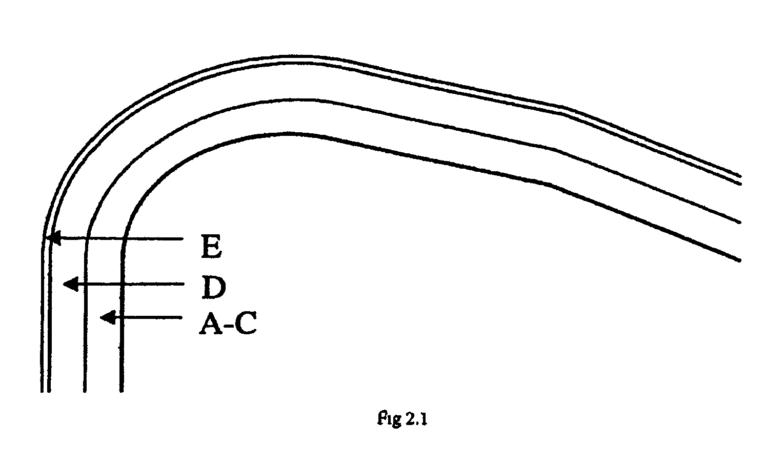
The present invention relates to a cutting insert particularly for turning of stainless steel comprising a cemented carbide substrate and a post-treated coating witha substrate of cemented carbide having a composition of from about 5.0 to less than about 8.0 wt % Co, from about 3.0 to about 8.0 wt % cubic carbides of the metals Ti, Ta and Nb with a Ti / (Ti+Ta+Nb) ratio of from about 0.05 to about 0.3 and balance tungsten carbide (WC) having a grain size of from about 1.5 to about 3.5 μm in the as-sintered state. Further, the substrate has a surface zone of from about 5 to about 30 μm characterized by an enrichment of binder phase and a depletion of cubic carbides,and a coating having a first, innermost layer system of one or several layers of TiCxNyOz with x+y+z≦1 with a total thickness of from about 0.7 to about 5.5 μm and a second multilayer system consisting of from about 5 to about 31 alternating layers of Al2O3 and TiCxNyOz (x+y+z≦1), preferably κ-Al2O3 and TiN, the Al2O3-layers having an individual layer thickness of less than about 0.5 μm and the TiCxNyOz-layers less than about 0.2 μm with a total thickness of the multilayer of from about 1.0 to about 5.0 μm. The multilayer is exposed along the edge line and into the rake and flank face. In an alternative embodiment the multilayer is replaced by an Al2O3-layer.

Description

BACKGROUND OF THE INVENTION[0001]The present invention pertains to a coated cemented carbide metal cutting tool for the machining of steels in general when a high wear resistance as well as a large toughness behaviour of the cutting edge are required. The tool is particularly suitable for turning of stainless steels.[0002]When cemented carbide cutting tools are used in the machining of steels, the tool is worn by different mechanisms such as abrasive and chemical wear, chipping and fracturing of the cutting edge. For a coated tool normally having thin surface layers of wear resistant carbide, nitride, carbonitride and / or oxide compounds formed by various vapor deposition techniques, the coating contributes to increase the abrasive wear resistance. But it also acts as a thermal barrier for the diffusion of heat from the cutting surface into the underlying cemented carbide substrate. A high temperature within the edge region in combination with high cutting forces result in an increas...

Claims


Application Information

Patent Timeline
Patent Type & Authority Patents(United States)
IPC IPC(8): B32B9/00C23C16/00C23C16/30
CPCC22C29/08C23C28/044C23C28/42C23C28/042C23C30/005B22F2005/001Y10T428/24628Y10T428/24975Y10T428/265C23C16/00B23B27/14
Inventor CEDERGREN, GUNILLALINDHOLM, MIKAELLJUNGBERG, ANN-BRITTLAGERQUIST, MIKAELCULLIN, FRIDA
Owner SANDVIK INTELLECTUAL PROPERTY AB
Why Eureka
Try Eureka