
Machine tool for cutting pipe

A machine tool and pipe cutting technology, which is applied in the field of mechanical devices, can solve problems such as low feeding accuracy and efficiency, low cutting accuracy, and energy waste, and achieve the effects of improving work efficiency, cutting efficiency, and saving power

Active Publication Date: 2008-10-08
山东德晟机器人股份有限公司
View PDF0 Cites 30 Cited by
  • Summary
  • Abstract
  • Description
  • Claims
  • Application Information

AI Technical Summary

Problems solved by technology

At present, the general pipe cutting machine tools on the market are all stationary, and the pipes to be cut are rotated and then cut, which causes a waste of energy during the pipe rotation.
At the same time, the cutting accuracy of existing pipe cutting machine tools is low, and the accuracy and efficiency of feeding are low, which ultimately leads to low yield

Method used


Image

  • Machine tool for cutting pipe
  • Machine tool for cutting pipe
  • Machine tool for cutting pipe

Examples


Embodiment Construction

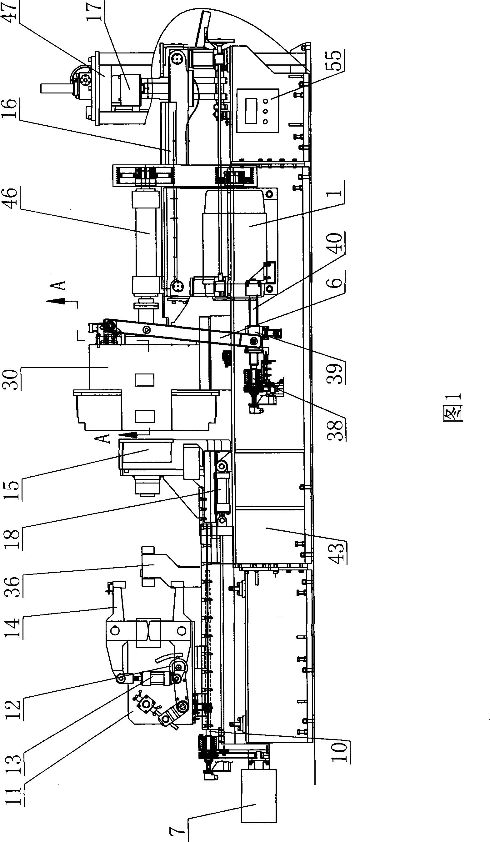
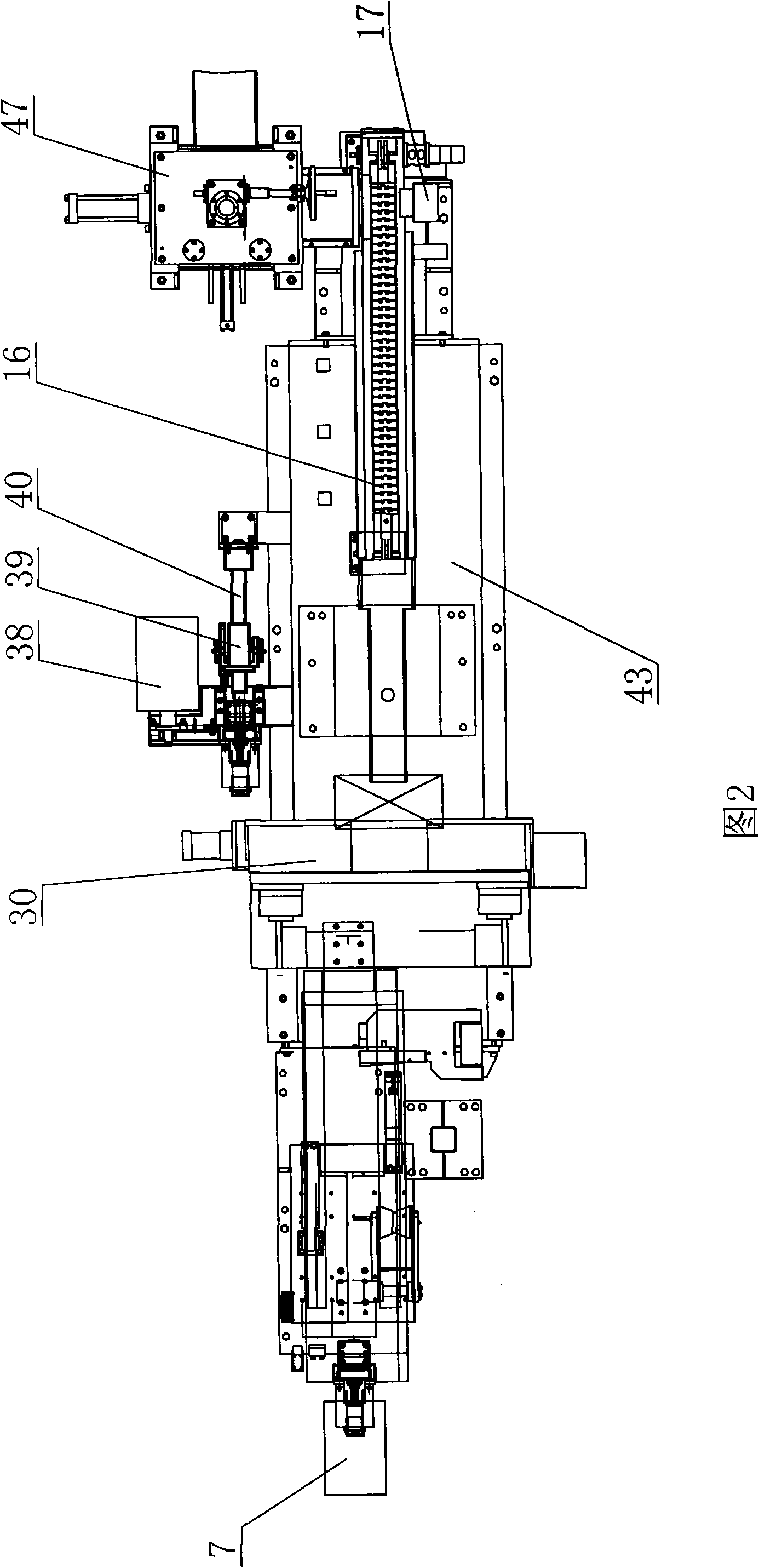
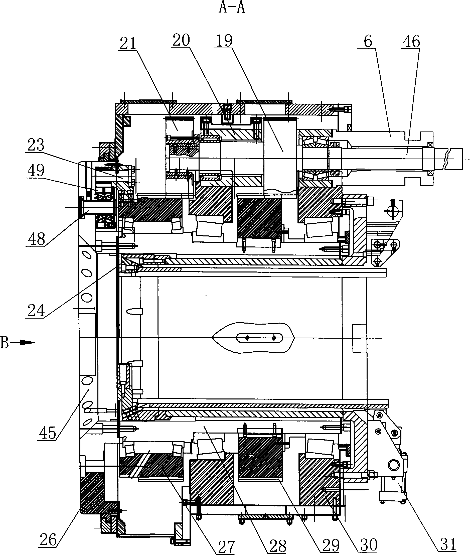
[0008] A pipe cutting machine tool, comprising a machine bed body 43, a spindle box 30, a main motor 1, a feeding device and a clamping device are installed on the machine tool bed body 43, a main shaft 28 and a transmission shaft 46 are installed in the spindle box 30, and the main motor 1 is The device is connected with the transmission shaft 4, and the main motor 1 can be connected with the transmission shaft 46 through a gear transmission, or can be connected with the transmission shaft 4 through a transmission belt. The first main drive helical gear 29 and the first feed helical gear 27 are installed on the main shaft 28, bearings are arranged between the first feed helical gear 27 and the main shaft 28, the cutter head 26 is installed at one end of the main shaft 28, and the cutter 45 is installed on the cutter head 26, The second main transmission helical gear 19 and the second feed helical gear 21 are installed on the drive shaft 46, the second main transmission helical...


PUM


Abstract

The invention discloses a tube-cutting machine tool, comprising a machine tool body which is provided with a main shaft box, a main motor, a feeding device and a clamping device; the interior of the main shaft box is provided with a main shaft and a transmission shaft, the main motor is connected with the transmission shaft by a transmission device, a first main transmission bevel gear and a first feed bevel gear are arranged on the main shaft, one end of the main shaft is provided with a tool pan, a tool is arranged on the tool pan, a second main transmission bevel gear and a second feed bevel gear are arranged on a transmission shaft, a feed box is arranged on the transmission shaft, a feed power and transmission device is arranged on the machine tool body, the feed power and transmission device is connected with the feed box, a first feed transmission block is arranged on the first feed bevel gear, a second feed transmission block is arranged on the tool pan, and a transmission direction-changing device is arranged between the first feed transmission block and the second feed transmission block. The tube-cutting machine tool can realize the automatic feed, automatic size fixation and automatic clamping, the tool can carry out the automatic feed and withdrawal, and the clamping device can be released automatically after the processing, thus automatically transmitting the finished product and greatly improving the working efficiency.

Description

technical field [0001] The invention relates to the field of mechanical devices, in particular to a pipe cutting machine tool. Background technique [0002] At present, the pipe cutting machine tool is a kind of machine tool equipment commonly used in industrial production, which can cut pipes. At present, the general pipe cutting machine tools on the market all have the cutters stationary, and the pipes to be cut are rotated and then cut, which causes a part of energy to be wasted during the pipe rotation. At the same time, the cutting precision of the existing pipe cutting machine tools is low, and the precision and efficiency of feeding are low, which ultimately results in low yield. Contents of the invention [0003] The purpose of the present invention is to provide a pipe cutting machine tool. When cutting, the tool rotates with the spindle at high speed, and the pipe to be cut remains stationary, which saves energy, and at the same time greatly improves the cutting...

Claims


Application Information

Patent Timeline
IPC IPC(8): B23D21/04B23Q5/28B23D33/02B26D1/12B26D5/00B26D7/01B26D7/06B26D7/18
Inventor 赵胜林侯志清王建立
Owner 山东德晟机器人股份有限公司
Learn More