

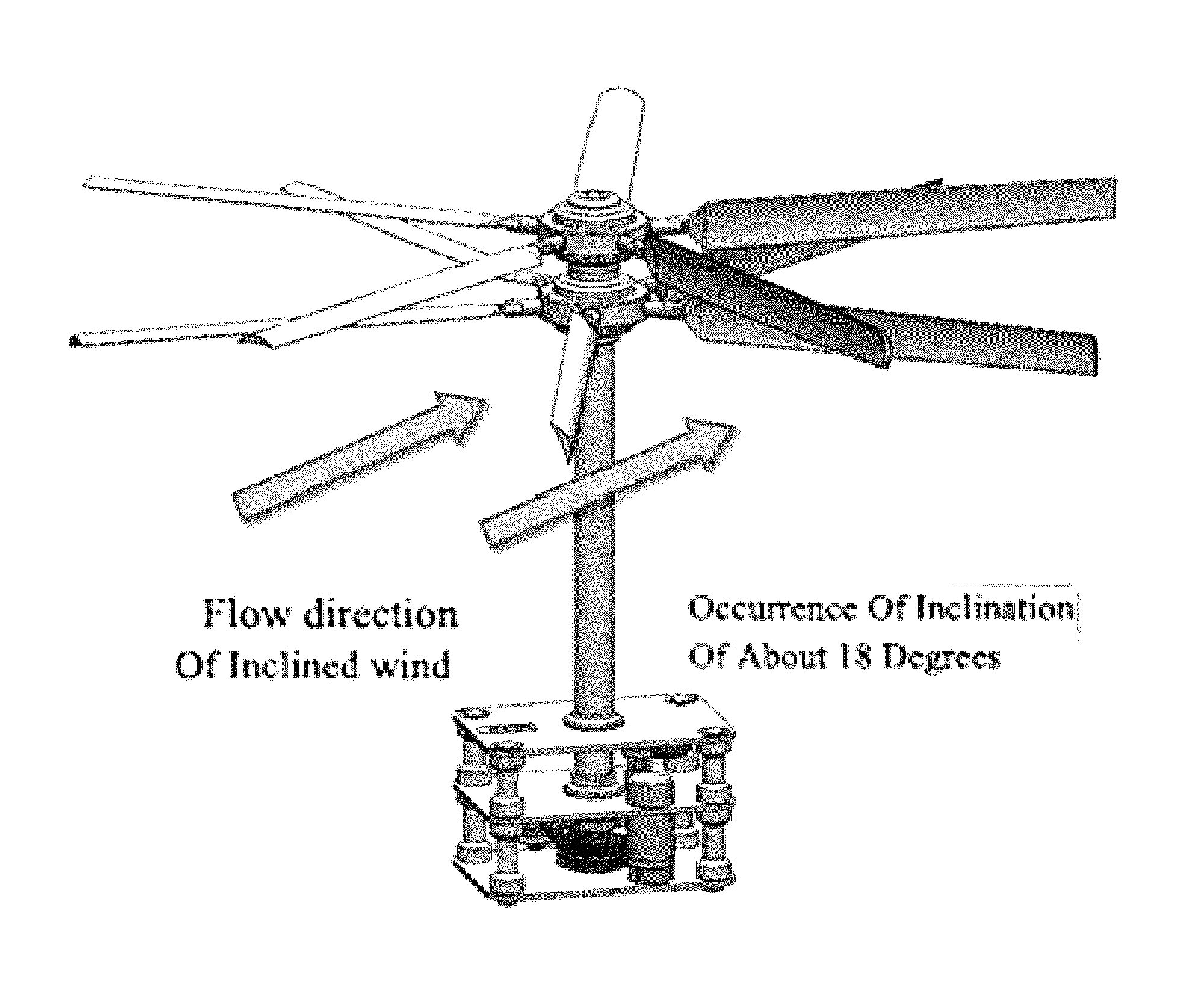
High-performance wind turbine generator that can be driven in horizontal/vertical axis directions with the use of 3D active intelligent turbine blades
a technology of intelligent turbine blades and turbine blades, applied in the direction of electric generator control, renewable energy generation, greenhouse gas reduction, etc., to achieve the effect of improving energy efficiency, simple and efficient operation, and optimal mounting distan
- Summary
- Abstract
- Description
- Claims
- Application Information
AI Technical Summary
Benefits of technology
Problems solved by technology
Method used
Image

Examples
Embodiment Construction
[0047]Reference will now be made in detail to the preferred embodiments of the present invention, examples of which are illustrated in the accompanying drawings. Wherever possible, the same reference numbers will be used throughout the drawings to refer to the same or like parts.
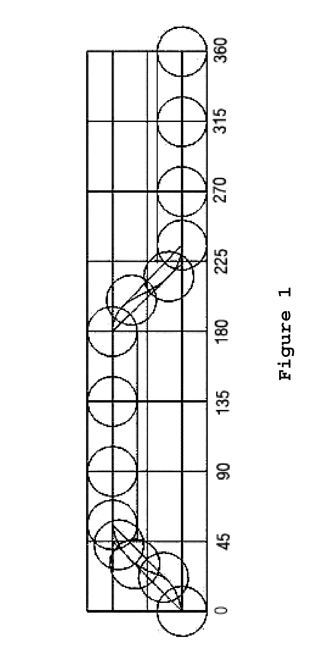
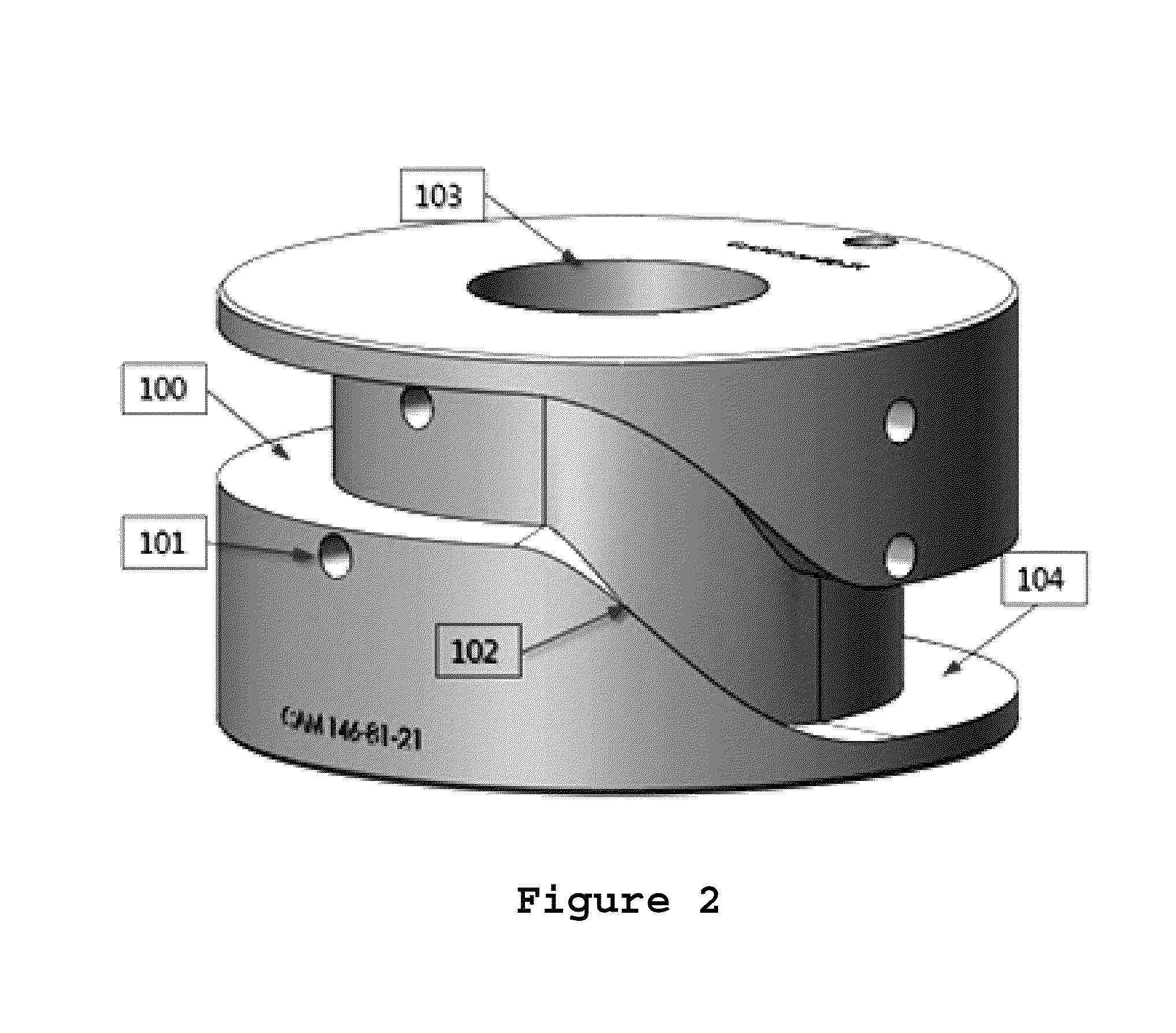
[0048]A repeatedly circulating mechanism which is capable of satisfying various conditions required for the present invention may be considered as a cylindrical cam. Here, azimuth areas of ascending and descending areas of a roller of a cam follower may be respectively set to a width of about 60 degrees so that shock and vibration applied to the cam follower are minimized in a vertical height transition area within a guide route of the cam. Also, the transition area may be designed using a 8th power polynomial equation type and a cycloidal motion type to minimize the shock and vibration. In addition, two kinds of cams may be designed to maximally obtain a high-speed RPM. A cam (see FIG. 2) having a flat guid...
PUM
 Abstract
Description
Claims
Application Information