
Multi-edge chisel

a multi-edge, chisel technology, applied in the field of chisel, can solve the problems of increased risk of injury, increased risk of striking hammer, increased heft of striking hammer, etc., and achieve the effect of reducing shock

Inactive Publication Date: 2012-11-01
POOLE HLDG
View PDF7 Cites 0 Cited by
  • Summary
  • Abstract
  • Description
  • Claims
  • Application Information

AI Technical Summary

Benefits of technology

[0009]An object of the invention is to provide a chisel, which when used, facilitates protection of the user's hands, specifically the hand holding the chisel in place while the chisel is struck with a striking instrument. A feature of the invention is the striking surface is surrounded by cross guards which extend laterally at angles from the direction of the impact force. An advantage of these guards is that they redirect mis-strikes to the impact surface of the chisel. An advantage of the invention is that it prevents injury to the hands of the user even if a complete mis-strike occurs.
[0010]Another object of the invention is to provide a chisel which allows hands-free operation of the chisel. A feature of the invention is that the aforementioned cross guards provide a means for elevating an impact end of the chisel on a support surface such that the impact end is higher than the blade end of the chisel. An advantage of the invention is that the chisel can be struck at its impact end without the requirement that the chisel be stabilized by a user's hands.
[0011]Yet another object of the invention is to provide a chisel having different cutting surfaces. A feature of the invention is that it includes multiple striking plates and therefore positions, with each striking position correlating to at least one corresponding chiseling blade. An advantage of the invention is that the type of cut performed by the chisel may be varied by the use of a different striking position.
[0012]Another object of the invention is to minimize shock to the hand holding the chisel. A feature of the invention is that the chisel is held in a variety of positions, off center of the direct path of force exerted by the striking tool. Another feature of the invention is that it allows multiple positions of hands when using the chisel in conjunction with a striking tool. An advantage of the invention is that the hand of the user does not experience the force applied to the tool by the striking tool.
[0013]An object of this invention is to create a surface on the chisel to convey information. A feature of the chisel is that in one embodiment, the chisel defines a substantially flat surface, where product information may be conveyed to the end user of the device. Another feature is that the chisel is adapted to receive a leveling indicator, in one embodiment of which is integrally molded with the handle of the chisel. An advantage of the invention is that multiple pieces of information may be related to the user through various means of printing, etching, or embedding on the designated surface of the tool.
[0014]Still another object of the invention is to create a durable chisel. A feature of the invention is that it comprises a high-strength inner core, which is encapsulated or integrally molded by impact resistant plastic. An advantage of the invention is that due to the use of plastic cover, the core component remains protected during use. Another advantage of the invention is that the encapsulation of the inner core provides thermal and electrical insulation.

Problems solved by technology

Further, the hand holding the chisel is subject to risk of injury should a mis-strike occur.
This risk increases as the heft of the striking hammer increases.

Method used


Image

  • Multi-edge chisel
  • Multi-edge chisel
  • Multi-edge chisel

Examples


Embodiment Construction

[0024]In describing exemplary embodiments of the marketing device of the present disclosure illustrated in the drawings, specific terminology is employed for the sake of clarity. The claimed invention, however, is not intended to be limited to the specific terminology so selected, and it is to be understood that each specific element includes all technical equivalents that operate in a similar manner to accomplish a similar purpose.

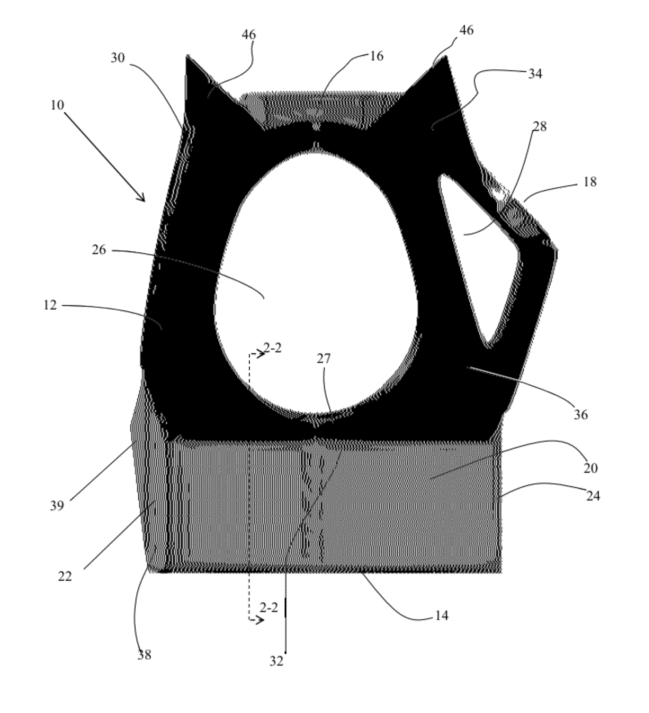
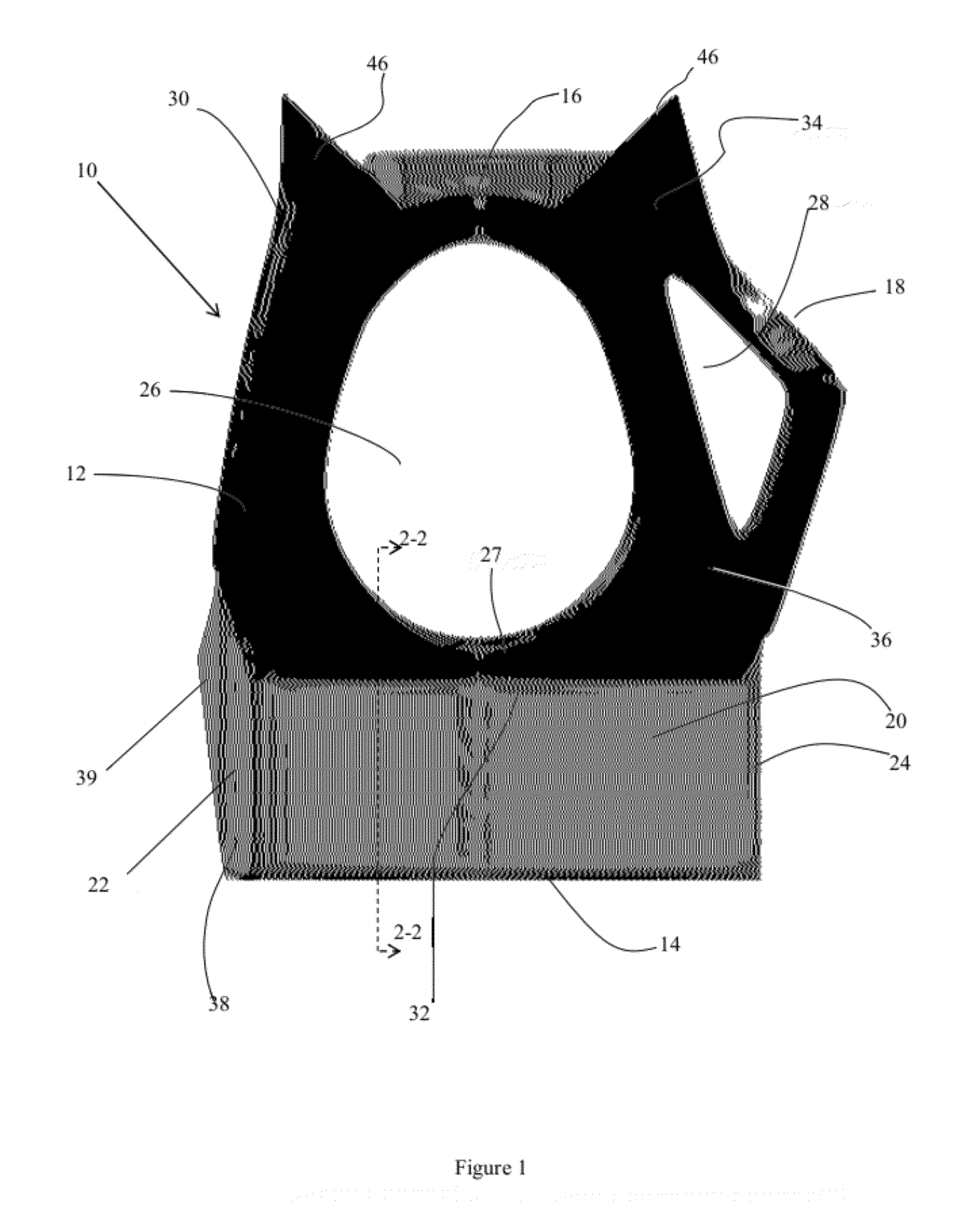
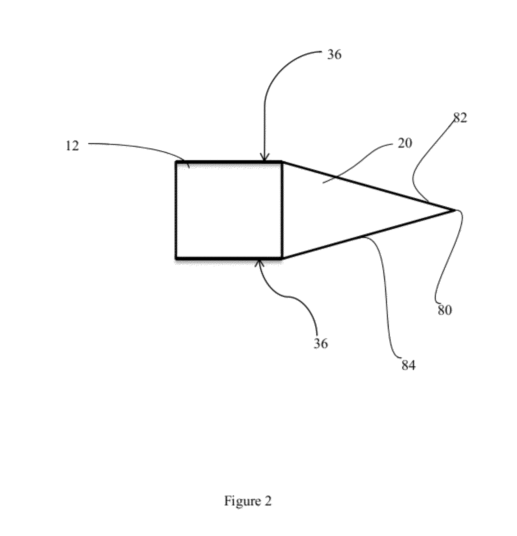
[0025]An embodiment of the multi-edge chisel is shown in FIG. 1 designated as numeral 10. As depicted therein, the multi-edge chisel 10 comprises a substantially flat body 12 such that at least a surface of the body is either co-planar to, or parallel to, the plane defined by a blade 20 of the chisel. The body 12 can be made out of any strike-resistant, non-deformable material. In the embodiment shown in FIG. 1, the body 12 incorporates a metallic core encapsulated by a strike resistant plastic encapsulation layer 36.

[0026]In one embodiment, the device 10...


PUM

PropertyMeasurementUnit
thicknessaaaaaaaaaa
thicknessaaaaaaaaaa
widthaaaaaaaaaa

Abstract

A multi-edge chisel which can be operated in a hands-free manner is made from a unitary main body with at least one opening. The main body has a flat profile, with a blade on one end, and at least one striking plate on the opposite end.

Description

CROSS REFERENCE TO RELATED APPLICATIONS[0001]This application claims the benefit as a utility of U.S. Provisional Application No. 61 / 481,006 filed on Apr. 29, 2011, currently pending.TECHNICAL FIELD[0002]The present disclosure relates generally to cutting implements, and, more particularly, to a chisel having multiple cutting edges, and multiple strike locations.BACKGROUND OF THE INVENTION[0003]Cutting implements, such as straight chisels, have been employed in the manual trades for many years. These cutting implements allow the user to chip or chisel away at a work surface or other material. Chisels are designed to be impacted by a striking implement, such as the head of a hammer. The striking imparts force on the chisel. Accordingly, chisels have been designed so as to convey the force from the striking implement to the blade.[0004]Chisels have drawbacks and suffer from many disadvantages. While the chisel is designed to convey striking force to the blade, the chisel must be held ...

Claims


Application Information

Patent Timeline
Patent Type & Authority Applications(United States)
IPC IPC(8): B25D3/00B21K11/00
CPCB23P15/28B21K5/12B25D3/00
Inventor HANLON, JARED W.
Owner POOLE HLDG
Learn More