Power Take Off Control System

a control system and power take off technology, applied in the field of power take off control system, can solve the problems of a large amount of shock when a drive is initially provided to a large-sized implement, and achieve the effects of reducing the process load of the target control characteristics generating means, reducing shock, and reducing shock

Active Publication Date: 2009-08-27
KUBOTA LTD
View PDF13 Cites 0 Cited by
  • Summary
  • Abstract
  • Description
  • Claims
  • Application Information

AI Technical Summary

Benefits of technology

[0010]According to one preferred embodiment of the present invention, pre-recorded control characteristics are employed and the target control characteristics are generated. This obviates the need to generate the entirety of the target control characteristics when the PTO clutch is shifted from the disengaged state to the engaged state, and enables pre-recorded control characteristics to be partially employed. Furthermore, new appropriate target control characteristics can be generated merely by modifying the pre-recorded control characteristics. The process load of the target control characteristics generating means can be reduced thereby.
[0011]According to another preferred embodiment of the present invention, the target control characteristics generating means generates target control characteristics in accordance with the speed at which the clutch operation tool is operated. According to this embodiment, when the clutch operation tool is suddenly moved from the disengaged position to the engaged position, the PTO clutch is suddenly switched from the disengaged state to the engaged state. When the clutch operation tool is moved slowly from the disengaged position to the engaged position, the PTO clutch is slowly switched from the disengaged state to the engaged state. For example, when a small-sized implement is coupled to the machine body, the operator can suddenly move the clutch operation tool from the disengaged position to the engaged position. This causes the PTO clutch to be suddenly switched from the disengaged state to the engaged state, power to be quickly transmitted, and the small-sized implement to be driven without delay. When a large-sized implement is coupled to the machine body, the operator can move the clutch operation tool slowly from the disengaged position to the engaged position. This causes the PTO clutch to slowly switch from the disengaged state to the engaged state, power to be slowly transmitted, and shock to be minimized.
[0012]More specifically, according to a preferred embodiment, there is provided a sensor for detecting the operational behavior of the clutch operation tool, and when the clutch operation tool is operated at a speed that is greater than a previously set control reference speed, the target control characteristics generating means uses pre-recorded control characteristics for the target control characteristics. This makes it possible to avoid the problem of the PTO clutch being switched from the disengaged state to the engaged state unusually quickly, and shock increasing when the implement is driven. The problem can be avoided even when the operator mistakenly moves the clutch operation tool from the disengaged position to the engaged position unusually quickly.

Problems solved by technology

In contrast, the weight of the driven part and the starting torque of a large-sized implement (for example, a large grass mower) are comparatively large, and therefore when the PTO clutch is moved to the engaged state and power is transmitted to the large-sized implement, the shock when a drive is initially provided to the large-sized implement is a comparatively great amount.

Method used


Image

  • Power Take Off Control System
  • Power Take Off Control System
  • Power Take Off Control System

Examples


Embodiment Construction

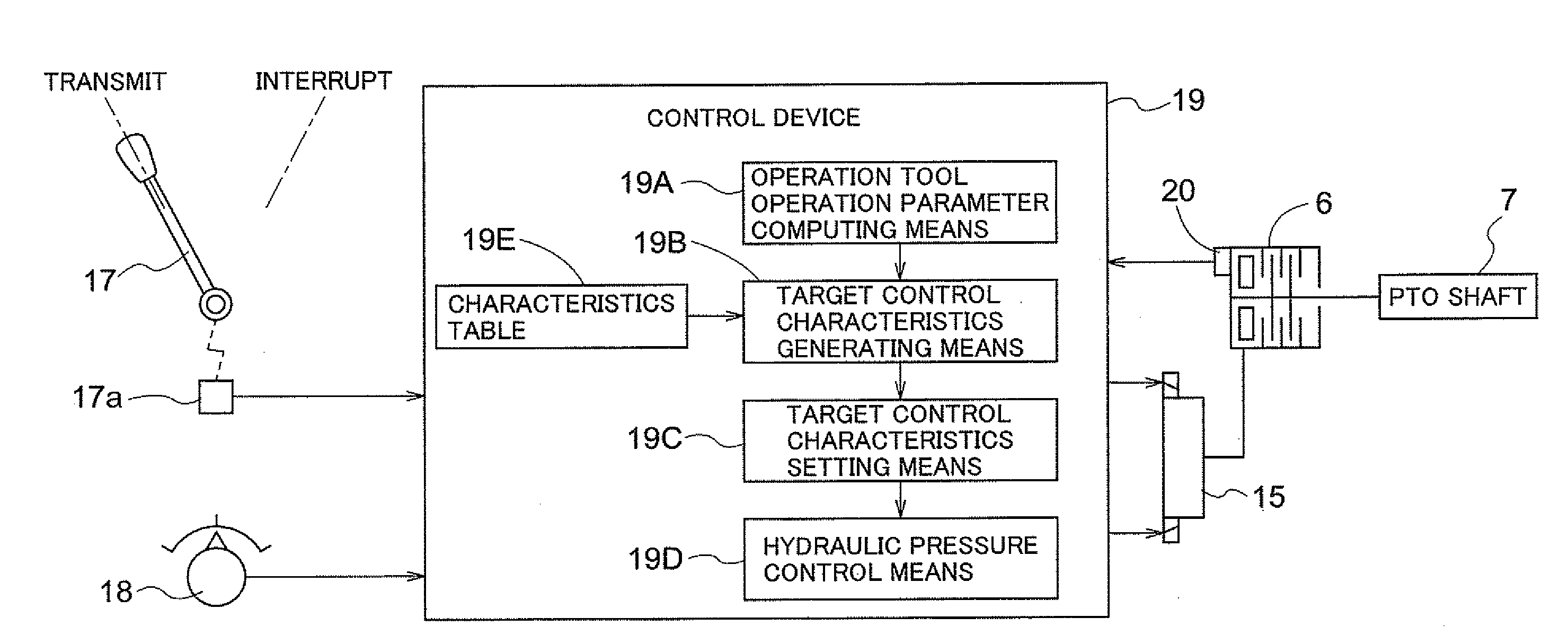
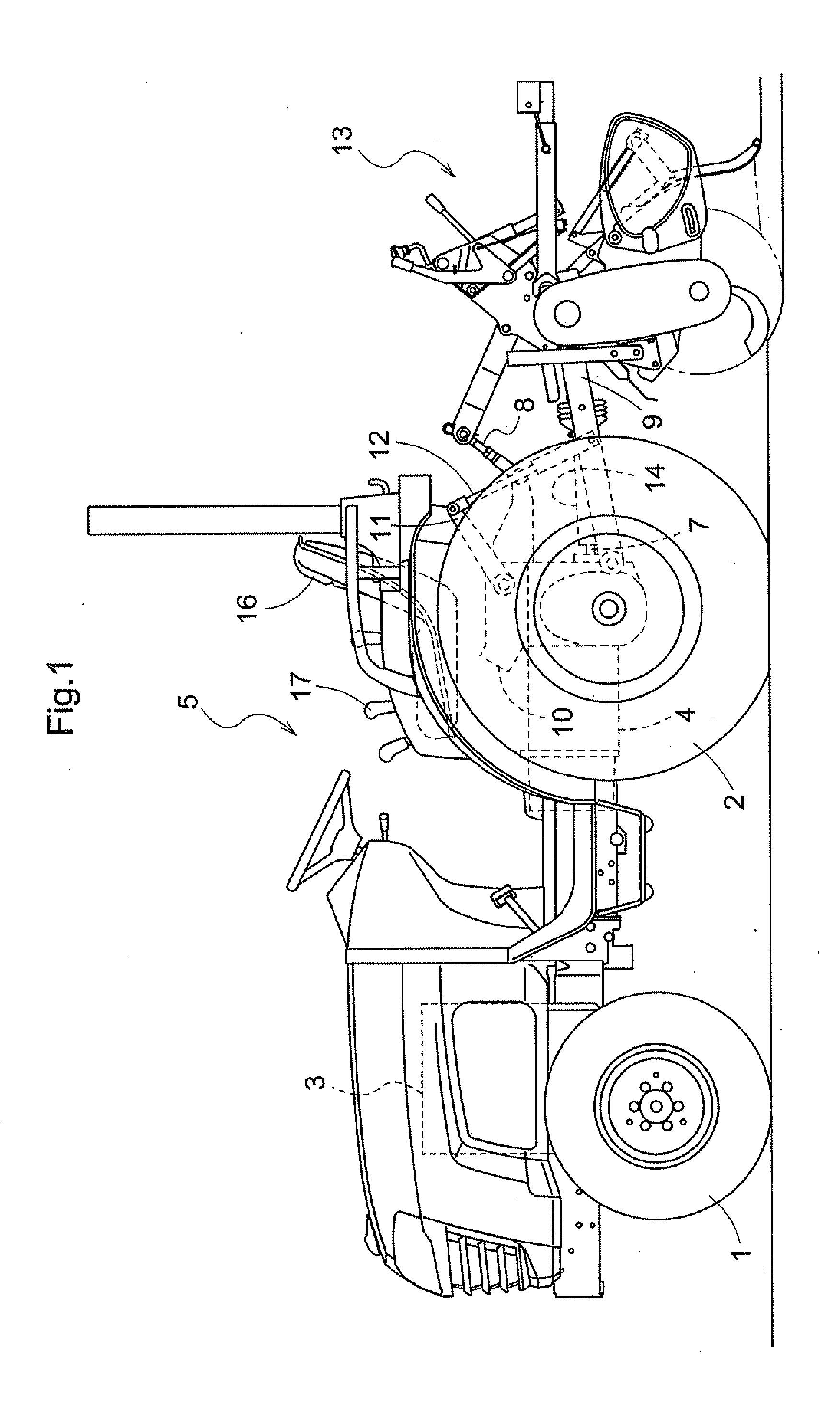
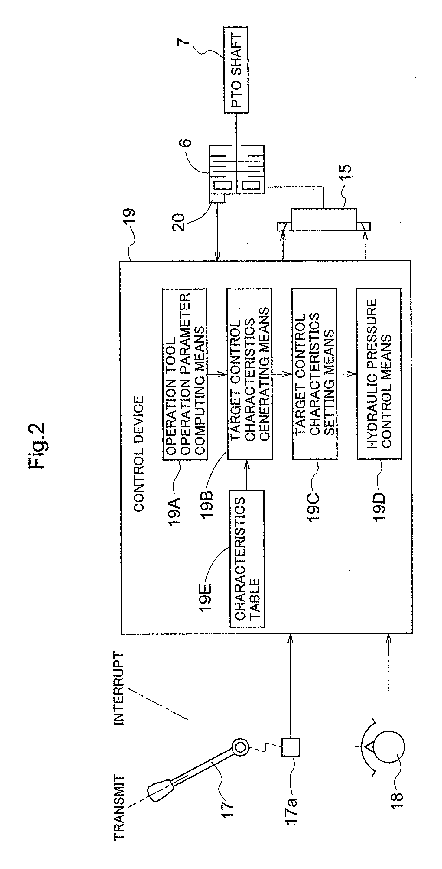
[0019]A tractor, which is one example of a work vehicle, is shown in FIG. 1. The tractor has right and left front wheels 1 that can be steered to the right and left, right and left rear wheels 2, an engine 3, a transmission casing 4, and an operator part 5. As can be understood from FIGS. 1 and 2, the power generated by the engine 3 is transmitted to the front wheels 1 and the rear wheels 2 via a hydrostatic continuously variable speed change device (not shown) and a gearshift-type secondary speed change device (not shown) provided to the transmission casing 4. The power generated by the engine 3 can also be transmitted to a PTO shaft 7 provided to a rear part of the transmission casing 4, via a PTO speed change device (not shown) and a PTO clutch 6 provided to the transmission casing 4.

[0020]As shown in FIG. 1, a top link 8 and right and left lower links 9 are supported on the rear part of the transmission casing 4 so as to be capable of moving upward and downward, a lift arm 11 th...


PUM


Abstract

A power take-off (PTO) control system for a work vehicle equipped with an implement, comprising a hydraulic multi-plate PTO clutch (6) whereby power from the work vehicle is interruptibly transmitted to the implement; a control valve (15) for adjusting an actuating pressure of the PTO clutch; a manually operable clutch operation tool (17, 21) for sending an operation instruction to the control unit; and a control unit (19) for switching the PTO clutch from a disengaged state to an engaged state by controlling the control valve on the basis of the target control characteristics in response to the operation instruction of the clutch operation tool (17, 21). The target control characteristics are generated and set on the basis of the operational behavior of the clutch operation tool (17, 21).

Description

BACKGROUND OF THE INVENTION[0001]1. Field of the Invention[0002]The present invention relates to a power take off (PTO) control system for a work vehicle equipped with an implement, and particularly to hydraulic control of a PTO clutch.[0003]2. Description of the Related Art[0004]A tractor disclosed in Japanese Laid-open Patent Publication No. 2006-11843, which is one example of a work vehicle, comprises a hydraulic multi-plate PTO clutch that is able to transmit and interrupt power to an implement coupled to a machine body (see C3 of FIGS. 3 and 4 of the abovementioned document), a control valve for supplying hydraulic fluid to the PTO clutch (V4 of FIG. 7 of Patent Document 1), and a PTO clutch lever (43 of FIG. 7 of the abovementioned document). A driver operates the control valve in the tractor by operating the PTO clutch lever. When hydraulic fluid is supplied to the PTO clutch, the PTO clutch enters an engaged state, and when hydraulic fluid is discharged from the PTO clutch, ...

Claims


Application Information

Patent Timeline
Patent Type & Authority Applications(United States)
IPC IPC(8): G06F19/00
CPCB60K25/06F16D48/066F16D2500/1026F16D2500/10437F16D2500/70412F16D2500/525F16D2500/702F16D2500/70406F16D2500/31413B60K17/28B60W10/30
Inventor NAKAMURA, KENTAROHATTORI, AKIO
Owner KUBOTA LTD
Why Eureka
Try Eureka