Single supply level shifter

a level shifter and single supply technology, applied in logic circuits, logic circuit coupling/interface arrangements, pulse techniques, etc., can solve problems such as congestion in circuit layout, extra pin counts, and limitations of conventional level shifters

Active Publication Date: 2006-03-07
NORTH STAR INNOVATIONS
View PDF5 Cites 33 Cited by
  • Summary
  • Abstract
  • Description
  • Claims
  • Application Information

AI Technical Summary

Problems solved by technology

The conventional level shifter has limitations since it operates on dual supply voltages, i.e., both VDD and VDDa.
Extra connections lead to a congestion in the circuit layout, as well as extra pin counts.
Currently, the above-mentioned limitations are overcome by using a larger chip area, but this leads to an increase in fabrication cost.

Method used


Image

  • Single supply level shifter
  • Single supply level shifter
  • Single supply level shifter

Examples


Embodiment Construction

[0012]The following detailed description set forth below in connection with the appended drawings, is intended as a description of the presently preferred embodiments of the invention, and is not intended to represent the only form in which the present invention may be practiced. It is to be understood that the same or equivalent functions may be accomplished by different embodiments that are intended to be encompassed within the spirit and scope of the invention.

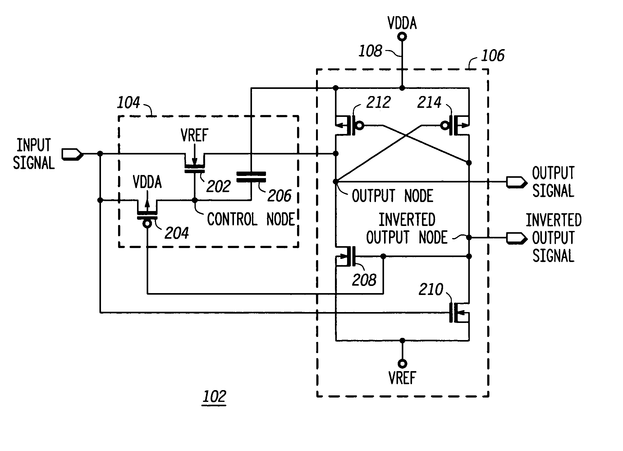
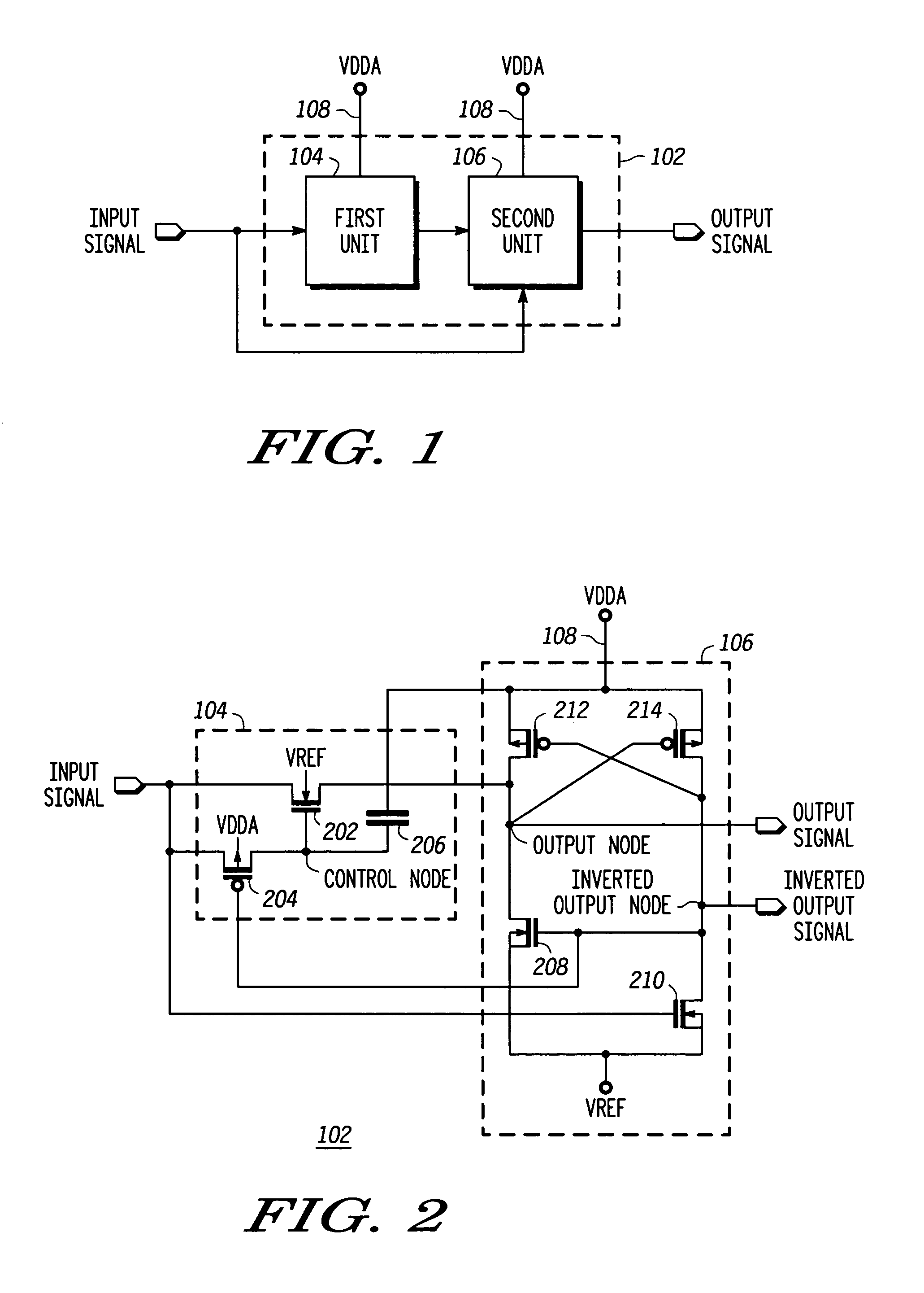
[0013]The present invention is a level shifter that operates using a single supply voltage source. The level shifter shifts a low supply voltage input signal to a higher supply voltage output signal. The level shifter includes a first unit and a second unit. The first unit is connected to a high power supply voltage source and receives the input signal. The first unit acts as a startup circuit such that when the level shifter is powered on, the first unit discharges an output node if the input signal is a logic low. The sec...


PUM


Abstract

A level shifter that shifts a low supply voltage input signal to a higher supply voltage output signal includes a first unit and a second unit. The first unit is connected to a high power supply voltage source and receives the input signal. The first unit acts as a startup circuit such that when the level shifter is switched on, the first unit discharges an output node if the input signal is a logic low, and when the input signal is a logic high, the first unit charges a control node to the voltage of the input signal. The second unit is connected to the first unit and the high power supply voltage source, and also receives the input signal. The second unit shifts the input signal to the higher supply voltage output signal. The level shifter operates only at the high power supply voltage.

Description

BACKGROUND OF THE INVENTION[0001]The present invention relates generally to digital logic circuits and, more particularly, to level shifter circuits for shifting a digital signal between two voltage levels.[0002]Digital logic circuits are widely used in the areas of electronics and computers. However, with advances in circuit technology, the various digital logic circuits that communicate with one another may operate at different power supply voltages. For example, a digital integrated circuit may include an input / output (I / O) section that operates at a first logic level, and a central logic core that operates at a second, lower supply voltage, since operating at the lower voltage reduces power consumption. On the other hand, the supply voltage for the I / O section must be kept at a higher supply voltage than the logic core to ensure a higher signal to noise ratio. For example, the I / O section may operate at supply voltages ranging from 3.3V to 5V, while the logic core operates at 0....

Claims


Application Information

Patent Timeline
Patent Type & Authority Patents(United States)
IPC IPC(8): H03K19/0175H03K3/356
CPCH03K3/356113H03K3/356008
Inventor KHAN, QADEER A.WADHWA, SANJAY K.MISRI, KULBHUSHAN
Owner NORTH STAR INNOVATIONS
Why Eureka
Try Eureka