

Multi-loop oscillator
- Summary
- Abstract
- Description
- Claims
- Application Information
AI Technical Summary
Benefits of technology
Problems solved by technology
Method used
Image


Examples
first embodiment
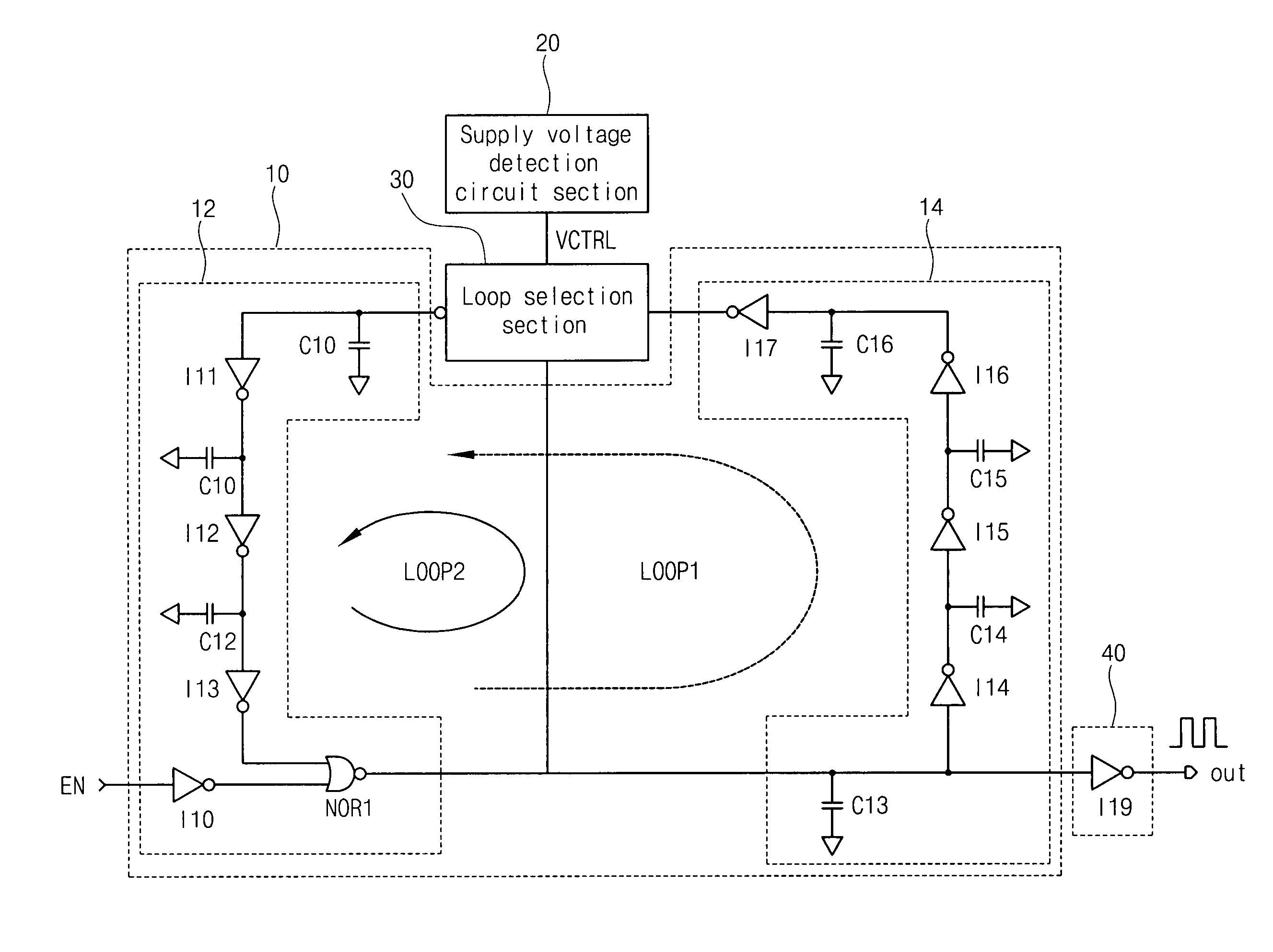
[0025]FIG. 2 is a circuit diagram of a dual-loop oscillator according to the present invention. The dual-loop oscillator operates while an enable signal EN is enabled to be at a high level.
[0026]The dual-loop oscillator according to the first embodiment of the present invention is a modified ring oscillator having two loops LOOP1 and LOOP2, and includes a loop circuit section 10, a supply voltage detection circuit section 20, a loop selection section 30, and an output section 40.
[0027]The loop circuit section 10 includes one loop between a first loop LOOP1 marked by a dotted line and a second loop LOOP2 marked by a solid line. Herein, the first loop LOOP1 is selected when a supply voltage is high and the second loop LOOP2 is selected when a supply voltage is low. That is, the first loop LOOP1 is a loop for generating a low frequency oscillation signal and the second loop LOOP2 is a loop for generating a relatively high frequency oscillation signal in comparison to the oscillation si...
second embodiment
[0044]FIG. 5 is a circuit diagram of a multi-loop oscillator according to the present invention. The multi-loop oscillator selects one loop from among “n” number of loops LOOP1 to LOOPn according to variation of a supply voltage, and outputs an oscillation signal having a corresponding frequency.
[0045]The multi-loop oscillator according to the second embodiment includes a loop circuit section 100, a supply voltage detection circuit section 200, a loop selection section 300, and an output section 400.
[0046]The loop circuit section 100 includes “n” number of loops LOOP1 to LOOPn having different signal transmission paths, in order to generate oscillation signals having different frequencies. Herein, loop delay times of the “n” number of loops LOOP1 to LOOPn are different from each other.
[0047]The Nth inverter chain section ICn includes inverters I101 to I103, capacitors C100 to C102, a first inverter I100, and a NOR gate NOR2. The inverters I101 to I103 are connected in series with ea...
PUM
 Abstract
Description
Claims
Application Information