Molded snap-together frame

a frame and snap-together technology, applied in the field of windows, can solve the problems of time-consuming and difficult mounting of windows using this system, substantial difficulties can develop, drawbacks in the conventional devices commonly employed, etc., and achieve the effect of reducing capital costs and eliminating any mold-to-mold discrepancy

Inactive Publication Date: 2006-03-14
L L CULMAT
View PDF48 Cites 66 Cited by
  • Summary
  • Abstract
  • Description
  • Claims
  • Application Information

AI Technical Summary

Benefits of technology

[0013]One feature of the present invention is the selected arrangement of alignment elements and joining elements around the outside of the perimeter wall so that two identical sub-assemblies can be joined together permanently by merely positioning the two sub-assemblies in a confronting relationship on opposite sides of a partition aperture and a desired architectural element, and pressing the two sub-assemblies together. The alignment elements assure proper alignment of the sub-assemblies so that the architectural element is suitably captured at the desired location within the partition aperture. The alignment elements also assure a retaining engagement is achieved between the joining elements so that the frame assembly and the architectural element, such as a window, is permanently retained in the partition aperture without need for any separate fasteners of any kind. This feature has the advantage of allowing very quick assembly of framed windows and other elements into partition apertures, particularly in assembly line situations.
[0014]Another feature o

Problems solved by technology

Unfortunately, there are many drawbacks in the conventional devices commonly employed for the installation of windows and the like within solid panels.
As a result, the mounting of windows using this system is time-consuming and difficult.
Further, if the precise pattern and the notches is not achieved, substantial difficulties can develop.
It is not possible to clip two of the first fram

Method used


Image

  • Molded snap-together frame
  • Molded snap-together frame
  • Molded snap-together frame

Examples


Embodiment Construction

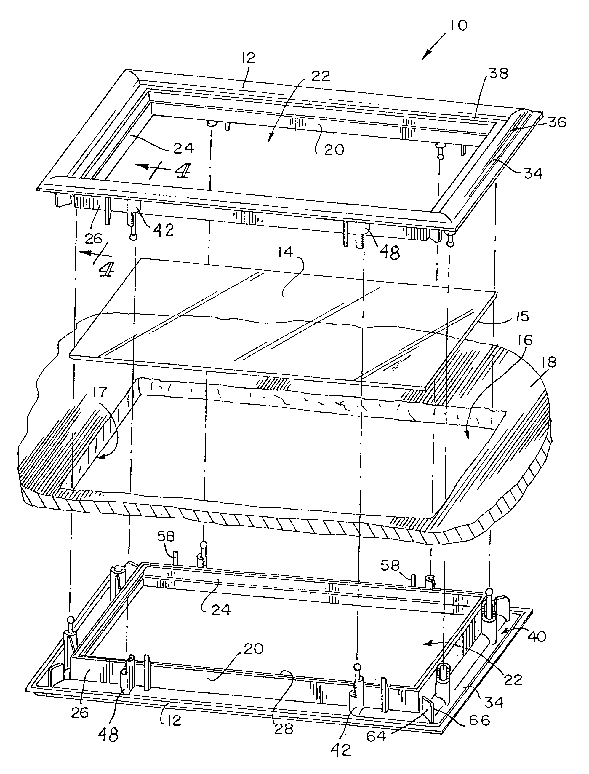
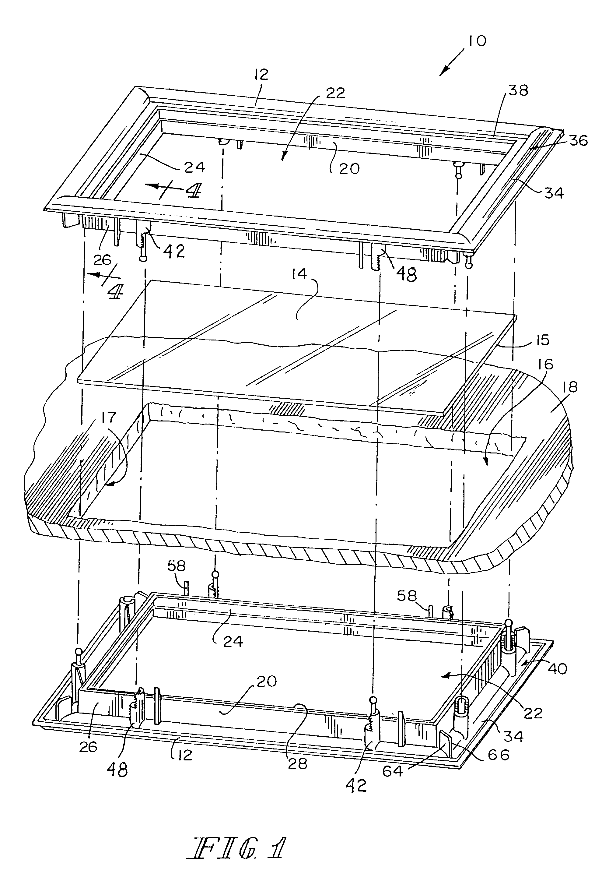
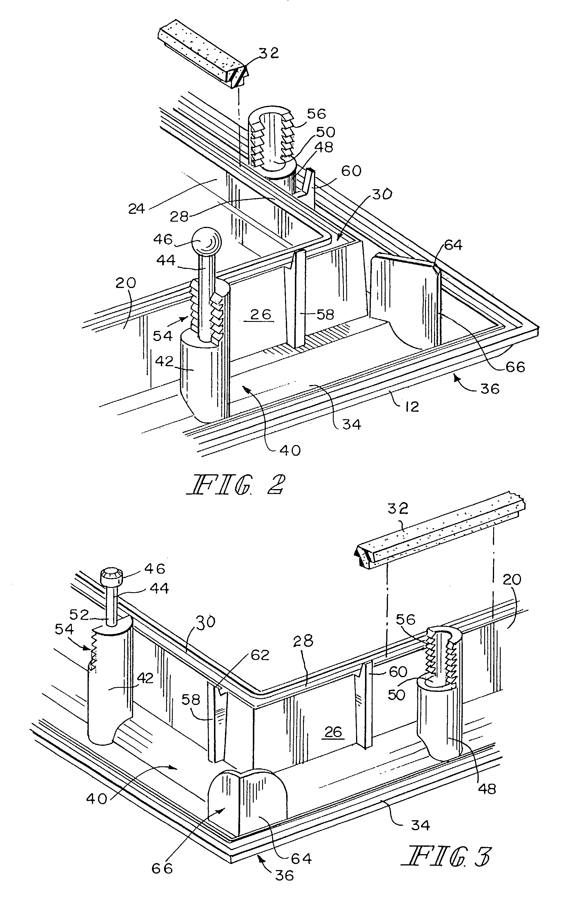
[0021]A frame assembly 10 of the present invention, shown in FIGS. 1–5 employs two identical sub-assemblies 12 placed in confronting relationship to each other on opposite sides of an architectural element 14 for incorporation into an aperture 16 in a partition 18. The illustrated architectural element 14 is a windowpane unit, but it will be appreciated by those skilled in the art that other architectural elements, such as vents or decorative panels and other devices, can be substituted for the windowpane unit without departing from the spirit of the present invention. The frame assembly 10 is illustrated to be rectangular, but it will be appreciated by those skilled in the art that other shapes for the frame assembly 10 and the corresponding aperture 16 can be accommodated by the present invention such as circular, square, octagonal, oval, and so forth. The partition 18 can be in the form of a fixed wall, a door, a divider, a partition or any other static or movable structural barr...


PUM


Abstract

A frame assembly is formed of two molded sub-assemblies, each sub-assembly being identical to the other. Each sub-assembly has a perimeter wall having an inner surface facing an opening and an outer surface to face a edge of an aperture in a partition. A first edge of the wall confronts a surface of the window while a flange projects outward from the outer surface of the perimeter wall. A plurality of joining elements are fixed to and project normally from the flange. Each joining element includes an alignment element and a locking surface to engage a similar surface on an aligned joining element of a confronting sub-assembly. The joining elements are arranged in a pattern that permits any two sub-assemblies made in the same mold to be permanently snapped together without the use of any separate fasteners.

Description

CROSS-REFERENCE TO RELATED APPLICATIONS[0001]This application is related to and claims all available benefits from U.S. Provisional Application Ser. No. 60 / 423,133, filed Nov. 1, 2002, which is hereby incorporated by reference in its entiretyBACKGROUND OF THE INVENTION[0002]The present invention relates to windows and other architectural elements that are coupled into a aperture in a partition by a surrounding frame. The present invention relates particularly to frame structures for such windows that are intended to capture a portion of the partition as well as the window between two confronting frame sub-assemblies.[0003]In many situations it is desirable to mount a window or other planar segment within an aperture in a wall, panel, or other partition. An example is the mounting of windows in panel doors such as garage doors, or other normally solid doors. Another example is the mounting of vents in the solid walls of trailers or campers.- Still another example is the mounting of d...

Claims


Application Information

Patent Timeline
IPC IPC(8): E06B3/96E06B3/00E06B3/58
CPCE06B3/5892
Inventor TUMLIN, RICKY W.UNDERWOOD, J. LARRY
Owner L L CULMAT
Why Eureka
Try Eureka