Grafted network incorporating a multiple channel fluid flow connector

a technology of fluid flow connector and graft material, which is applied in the field of coronary graft network, can solve the problems of time-consuming step, difficult suturing of such graft material, and high dexterity, and achieve the effect of minimizing any turbulent flow

Inactive Publication Date: 2006-03-14
QUATRO INVESTMENTS
View PDF50 Cites 16 Cited by
  • Summary
  • Abstract
  • Description
  • Claims
  • Application Information

AI Technical Summary

Benefits of technology

[0010]By means of the present invention, a grafted network is provided for enabling one or more coronary bypass procedures to be performed from a single relatively high fluid pressure source location. In addition, the grafted network of the present invention allows the bypass procedure to be performed directly at particular sites in the targeted vascular members requiring bypass blood flow thereto, with each of the direct sites being supplied with blood flow from a common singular bypass blood flow stream. Moreover, the grafted network of the present invention includes means for maintaining the supply bypass blood flow stream at high pressure while minimizing any turbulent flow effects through the grafted network, so as to consistently provide adequate bypass blood pressure and flow volume to each of the vascular members receiving such flow.
[0011]In a particular embodiment of the invention, one or more graft segments configured to operably transport bypass blood flow from a singular supply location to one or more delivery locations in a grafted network are provided in combination with one or more multiple channel blood flow connectors for directing such bypass blood flow in the grafted network to one or more vascular members. The blood flow connectors are configured for coupling, for example, first and second graft segments to a first vascular member defining a first blood flow delivery location. The blood flow connector preferably includes a supply conduit and a delivery conduit integrally formed therewith and adjacently disposed with respect to one another, with the supply conduit and the delivery conduit each having a distinct lumen formed therewithin. The supply conduit of the blood flow connector preferably includes first and second opposed open ends having annular recessed portions and annular lips for operably attaching respective open ends of the first and second graft segments thereto. The supply lumen and the delivery lumen are fluidly connected to one another through cooperating apertures in respective outer walls of the supply conduit and the delivery conduit at an intersection therebetween so as to provide for immediate bypass blood flow from the supply lumen to the delivery lumen. The delivery conduit includes at least one open end portion extending from the intersection and beyond an outer circumferential dimension of the supply conduit outer wall, such that a first open end of the delivery conduit is laterally spaced from, and extends beyond, the supply conduit outer wall. The delivery conduit is preferably configured for operable implantation directly into the targeted vascular member so as to provide bypass blood flow thereto. The delivery conduit is also preferably specifically sized to provide internal structural support for the targeted vascular member when the delivery conduit is implanted therein. Such internal structural support is preferably provided without damage to the vascular member, as commonly occurs with stent devices.

Problems solved by technology

While bypass procedures have been undertaken for some period of time, one particular and time consuming step is that of suturing the graft elements to respective portions of the patient's vasculature.
Because of the physical properties of, in particular, artificial biocompatible graft material, suturing of such graft material is often times difficult to complete.
The procedure is one which requires great dexterity, and when done at the site, is frequently in a zone with limited accessibility.
Graft systems proposed to date have drawbacks with regard to ease of implantation and securement into the patient's vasculature.
An additional issue that is not satisfactorily addressed in existing bypass techniques is the inability of such techniques to effectively maintain flow and pressure from a blood flow source such as the aorta to the vascular member in which the bypass procedure is conducted.
Accordingly, the substantial pressure drop between the respective bypass blood flow locations generally results in low flow volumes to the artery or other vascular member to which bypass flow is directed.
Previous attempts to provide sustained flow volumes to respective vascular members from a relatively high pressure source have been met with limited success, in that such systems proposed to date are difficult to manufacture and implement, and particularly difficult to produce positive reproducible implantation results.
In particular, such prior systems fail to provides components that may be quickly and effectively implanted in the surgical process.

Method used


Image

  • Grafted network incorporating a multiple channel fluid flow connector
  • Grafted network incorporating a multiple channel fluid flow connector
  • Grafted network incorporating a multiple channel fluid flow connector

Examples


Embodiment Construction

[0021]The objects and advantages enumerated above together with other objects, features, and advances represented by the present invention will now be presented in terms of detailed embodiments described with reference to the attached drawing figures which are intended to be representative of various possible configurations of the invention. Other embodiments and aspects of the invention are recognized as being within the grasp of those having ordinary skill in the art.

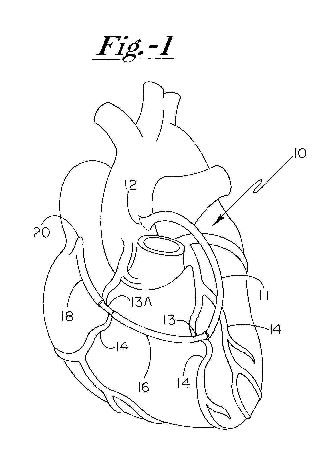
[0022]With reference to the enclosed drawing figures, and first to FIG. 1, a grafted network 10 includes a first graft segment 11 that is preferably attached by suture to a relatively high-pressure blood flow environment such as the aorta of a patient's heart, such as at location 12. Such location 12 comprises a singular supply location for directing blood through network 10 to one or more vascular members, such as coronary arteries 14.

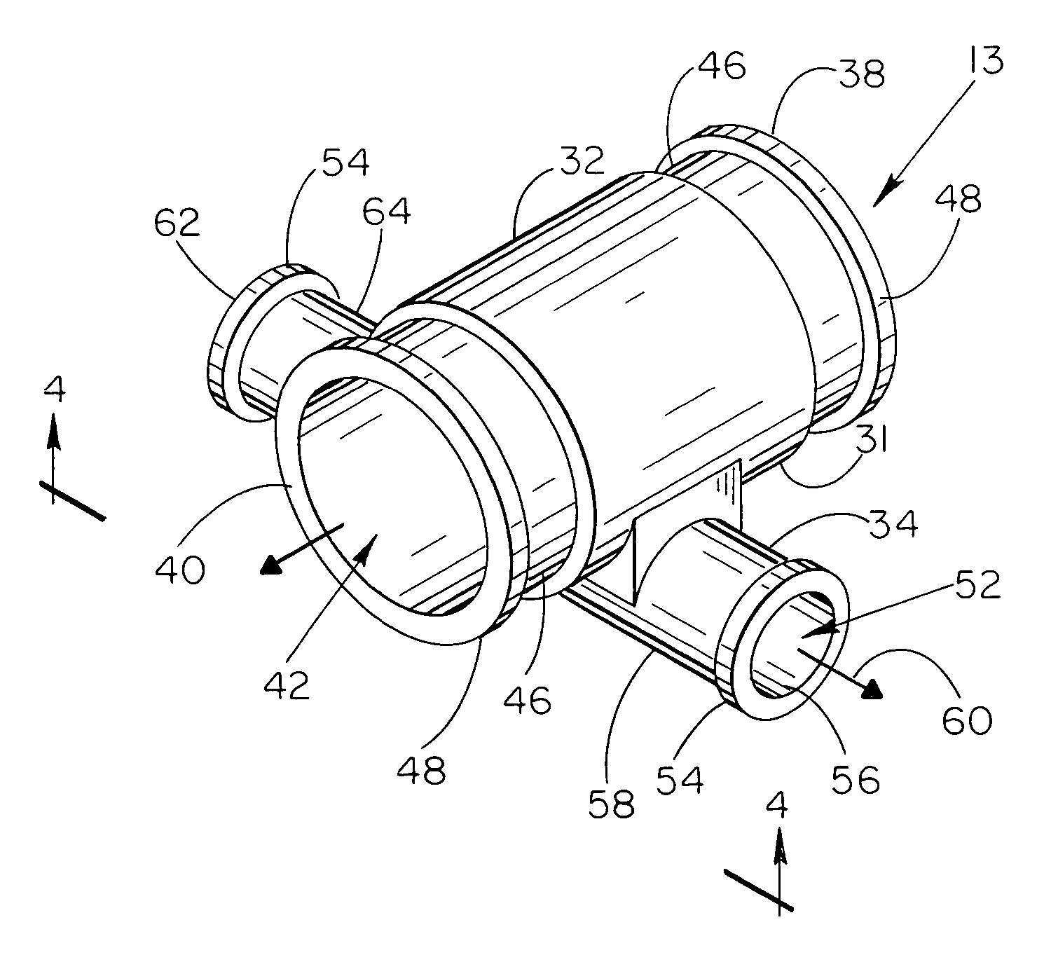
[0023]As illustrated in FIG. 1, first graft segment 11 is preferably secured to con...


PUM


Abstract

A grafted network including one or more graft segments for use in coronary bypass procedures and which are configured to operably transport bypass blood flow from a singular supply location to one or more delivery locations in the grafted network is provided in combination with one or more multiple channel blood flow connectors for directing such bypass blood flow in the grafted network to one or more vascular members requiring restorative blood flow thereto. The grafted network also preferably includes one or more devices for operably maintaining the grafted network under relatively high internal fluid pressure so as to continuously supply selective vascular members with adequate bypass blood flow.

Description

FIELD OF THE INVENTION[0001]The present invention relates to vascular graft networks generally, and more particularly to coronary graft networks incorporating one or more graft connectors that are specifically configured to efficiently transport bypass blood flow from a source to one or more delivery locations, which graft connectors may be directly implanted to the patient's vasculature at specific designated bypass locations.BACKGROUND OF THE INVENTION[0002]Coronary bypass surgery has become a common procedure, and is normally indicated for conditions requiring replacement and / or reconfiguration due to blockage of the coronary blood flow within a patient. To achieve such a bypass, grafts are surgically implanted to divert blood flow from a relatively high volume and pressure flow regime to a portion of the diseased vascular member downstream from the blockage therein. In typical bypass procedures, a section of the vascular system in a patient's body that has become impaired or ino...

Claims


Application Information

Patent Timeline
Patent Type & Authority Patents(United States)
IPC IPC(8): A61M5/00A61F11/00A61F2/04A61F2/06A61M25/18
CPCA61F2/064
Inventor VILLAFANA, MANUEL A.PALMQUIST, WILLIAM E.FLETCHER, BRUCE
Owner QUATRO INVESTMENTS
Why Eureka
Try Eureka