Object sensing apparatus

a technology of object sensing and object, which is applied in the direction of using reradiation, pedestrian/occupant safety arrangement, instruments, etc., can solve the problems of not being able to reliably use conventional object sensing apparatuses, affecting the functionality detecting defects in the sensor system during operation more accurately and reliably, so as to improve the functional dependability of the assistance system, the effect of improving the reliability of the assistance system

Inactive Publication Date: 2006-03-14
ROBERT BOSCH GMBH
View PDF19 Cites 75 Cited by
  • Summary
  • Abstract
  • Description
  • Claims
  • Application Information

AI Technical Summary

Benefits of technology

[0008]According to an example embodiment of the present invention, an object sensing apparatus is provided with which it may be possible to detect defects in the sensor systems during operation more accurately and more reliably, and thus to improve the functional dependability of an assistance system.
[0011]An example embodiment of the present invention thus may make possible a continuous self-diagnosis of the object sensing apparatus during normal vehicle operation, and thus a substantial improvement in the driving safety of the assistance system that uses the data of the object sensing apparatus.
[0013]In an example embodiment, three mutually independent sensor systems whose detection regions include a shared overlap region may be present. There exists in this case, for objects that are located in the shared overlap region, a capability not only for error detection but also for easily identifying the faulty sensor system by “majority decision,” and optionally for correcting the data, the alignment, or the calibration of the faulty system.
[0016]According to an example embodiment of the present invention, it may be provided to store the error signals furnished by the error recognition device together with the associated mutually contradictory measurement data, and thus to create error statistics that facilitate diagnosis when the object sensing apparatus is repaired or maintained.

Problems solved by technology

In some circumstances, an implausibility in the sensed data may also indicate a defect in the sensor system.
It general, however, it is not possible with conventional object sensing apparatuses reliably to detect misalignments or other defects in the sensor systems that negatively affect the functionality of the assistance system.
In this situation, the sensor systems operating independently of one another furnish redundant information that makes possible error detection while the apparatus is in operation.
If that is not the case—i.e. if the data contradict one another—it may be deduced therefrom that at least one of the participating sensor systems is defective, and an error signal is outputted.
In the event of a discrepancy, therefore, a fault in the stereo camera system is highly probable.

Method used


Image

  • Object sensing apparatus
  • Object sensing apparatus
  • Object sensing apparatus

Examples


Embodiment Construction

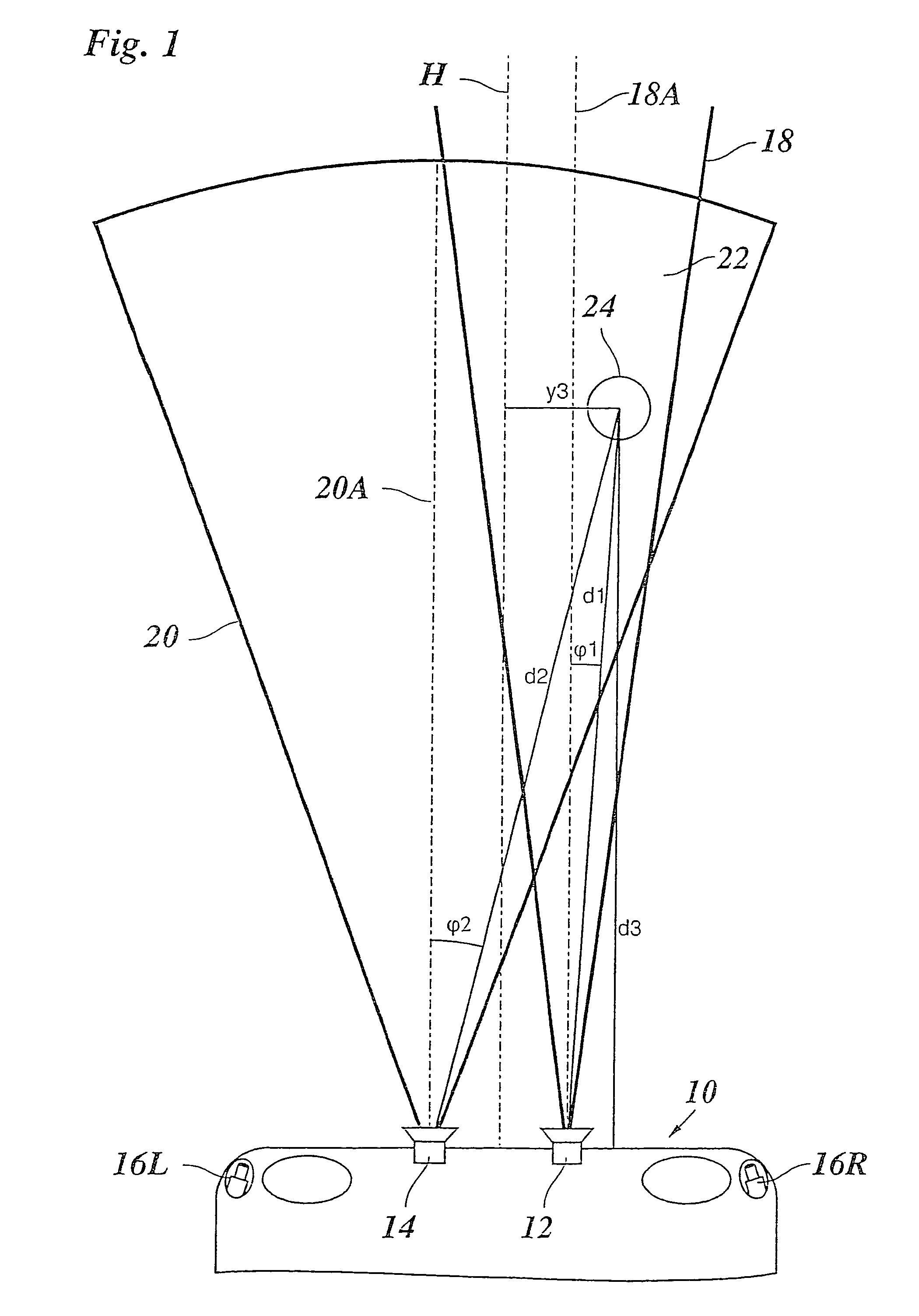
[0021]FIG. 1 illustrates, in a schematic plan view, the front part of a motor vehicle 10 that is equipped with three sensor systems operating independently of one another, namely a long-range radar 12, a short-range radar 14, and a video system that is constituted by two cameras 16L and 16R. Long-range radar 12 includes a detection region 18 having a range of, for example 150 m and a sensing angle of 15°, while short-range radar 14 includes a detection region 20 having a range of, for example, 50 m and a sensing angle of 40°. Between these detection regions 18, 20, which are not illustrated to scale in the drawings, there exists an overlap region 22. The detection region of the video system constituted by cameras 16L, 16R, however, which together will be labeled with the reference character 16, includes overlap region 22 (when visibility conditions are good). An object 24 that is located in this overlap region 22 may therefore be sensed by all three sensor systems.

[0022]Detection re...


PUM


Abstract

An object sensing apparatus for driver assistance systems in motor vehicles, including at least two sensor systems which measure data concerning the location and / or motion status of objects in the vicinity of the vehicle, and whose detection regions overlap one another, characterized by an error recognition device that checks the data measured by the sensor systems for absence of contradictions, and outputs an error signal upon detection of a contradiction.

Description

FIELD OF THE INVENTION[0001]The present invention relates to an object sensing apparatus for driver assistance systems in motor vehicles, including at least two sensor systems which measure data concerning the location and / or motion status of objects in the vicinity of the vehicle, and whose detection regions overlap one another.BACKGROUND INFORMATION[0002]Motor vehicles are increasingly being equipped with driver assistance systems that assist and provide support to the driver in driving the vehicle. One example of such an assistance system is a so-called adaptive cruise control (ACC) system, which automatically regulates the vehicle's speed to a desired speed selected by the driver or, if a preceding vehicle is present, adapts the speed in such a manner that a suitable distance from the preceding vehicle, monitored with the aid of a distance sensor, is maintained. Other examples of driver assistance systems are collision warning devices; automatic lane keeping systems (LKS), which...

Claims


Application Information

Patent Timeline
Patent Type & Authority Patents(United States)
IPC IPC(8): G01S13/93B60R21/00B60K31/00B60RB60R1/00G01S3/78G01S7/40G01S13/931G01S17/86G08G1/16
CPCB60K31/0008B60W30/16G01S7/40G01S13/931G01S13/867G01S2013/9325G01S17/023G01S2013/9332G01S2013/9375G01S2013/9321G01S13/865G01S13/87G01S2013/93271G01S2013/9315G01S17/86B60W2556/20
Inventor BRAEUCHLE, GOETZHEINEBRODT, MARTINBOCKER, JURGEN
Owner ROBERT BOSCH GMBH
Why Eureka
Try Eureka