
Partition coding method and device

a coding method and coding technology, applied in the field of partition coding methods and devices, can solve the problems of ambiguity introducing coding losses, inability to recognize the subjective quality of the image displayed, and the conventional methods of coding segmented pictures or partitions are usually considered rather expensive in terms of amount of bits,

Inactive Publication Date: 2006-03-14
KONINKLIJKE PHILIPS ELECTRONICS NV
View PDF5 Cites 3 Cited by
  • Summary
  • Abstract
  • Description
  • Claims
  • Application Information

AI Technical Summary

Benefits of technology

[0016]It is therefore an object of the invention to propose an improved method also using the type of contour grid previously defined, but leading to a more general and more efficient coding of the contour segments of the regions of a picture.

Problems solved by technology

Conventional methods of coding segmented pictures—or partitions—are usually considered as rather expensive in terms of amount of bits, e.g. an average value of 1,3 bit per pixel of contour with the so-called chain code technique.
Lossy shape coding techniques have therefore been proposed, but losses in shape information often result in an unacceptable degradation of the subjective quality of the image displayed on the basis of the decoded picture.
This ambiguity introduces coding losses.
Nevertheless the only possible error is the erroneous labeling of the central pixel of the cell, i.e. only of an isolated boundary pixel.
However, the MGCC approach previously described can only be used to code binary partitions.
In case of general segmented pictures, the partitions contain regions that share contours, and said approach is no longer appropriate.

Method used


Image

  • Partition coding method and device
  • Partition coding method and device
  • Partition coding method and device

Examples


Embodiment Construction

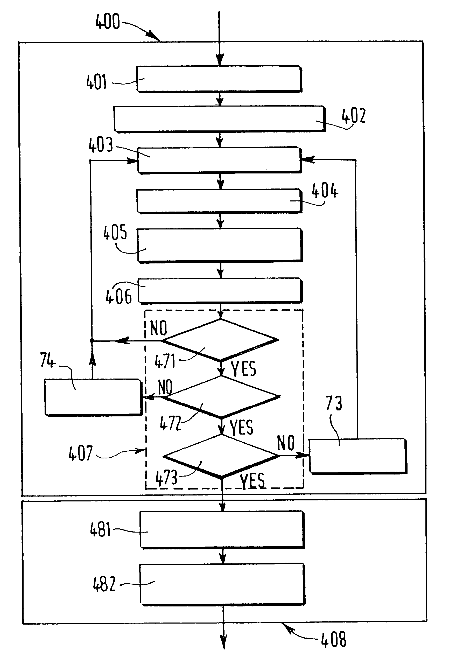
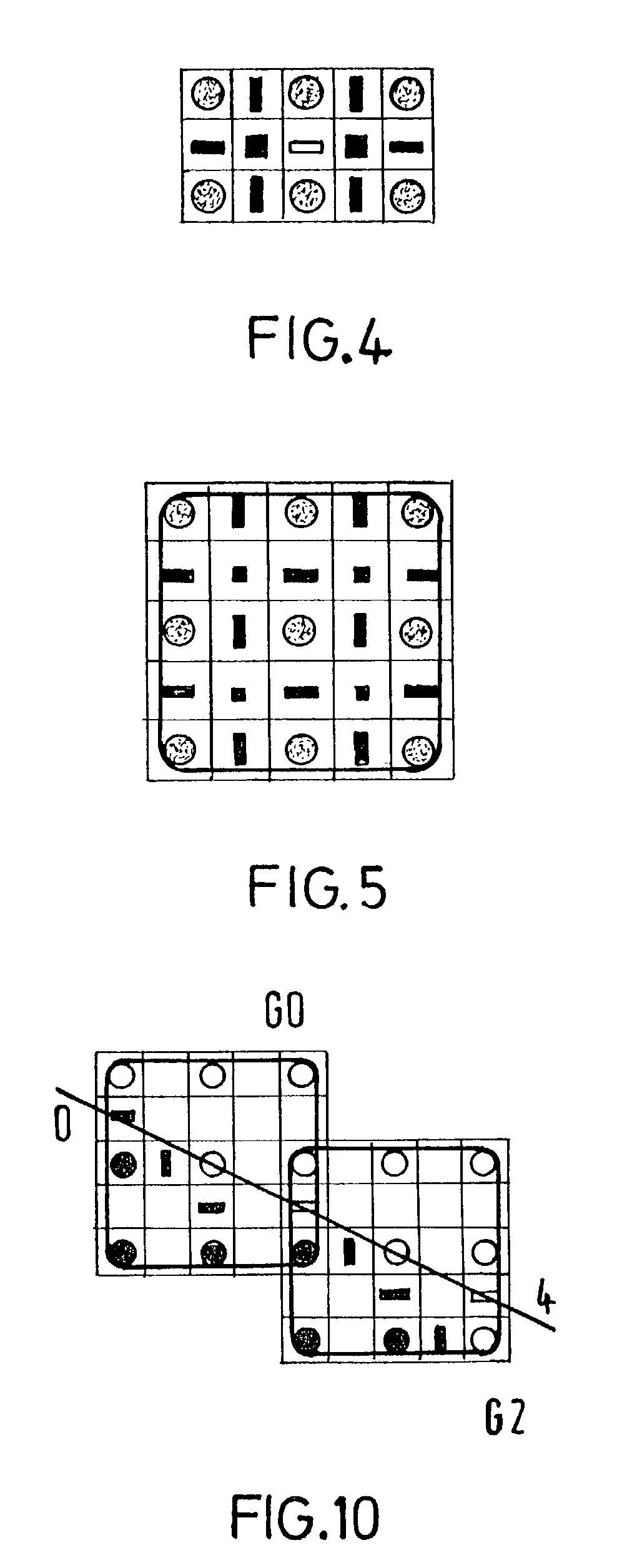
[0044]The flowchart of FIG. 17 corresponds to a basic scheme of an MGCC intra-mode encoding method according to the invention. This MGCC encoding process is applied on contour images defined on the type of contour grid described in relation with FIGS. 4 and 5. A partition, usually described in term of labels, must therefore be translated into a description of contour elements in the hexagonal grid. The main steps of the proposed method, carried out in the block designated by the reference 400 in FIG. 17, will be the following: generation of the contour image, extraction of the initial points from the picture, cell characterization, contour tracking, determination of the priority in the contour tracking, management of the multiple points, end of process, and extraction of the next initial point, these steps being followed by the final coding steps.

[0045]The first step 401 of the proposed method is provided for generating the contour pictures that will be later coded. The original par...


PUM


Abstract

The invention relates to a method of coding segmented pictures, or partitions, divided into homogeneous regions. Said method, called intra-mode coding process, comprises, for each successive partition, the steps of translating the picture of the labels associated to the regions into a description in terms of a contour element chain in which the elements are defined by means of their movements through successive basic cells, tracking inside each successive cell each contour from its initial contour point, previously extracted, to its end by storing chain symbols corresponding both to input, internal and output contour elements of said cell and to priorities between possible multiple outputs elements, and repeating these steps up to the end of each successive contour segment of the concerned partition. The information corresponding in each cell to the initial point of each contour segment and to the associated chain of movements between that initial point and the initial one of the following cell is finally coded.

Description

[0001]This application is a continuation of Ser. No. 09 / 406,651, filed Sep. 27, 1999, now U.S. Pat. No. 6,594,310.FIELD OF THE INVENTION[0002]The present invention relates to a method of coding segmented pictures, or partitions, divided into homogeneous regions to which specific labels are respectively associated, and to a corresponding device. This invention has mainly applications in relation with the MPEG-4 standard, for the implementation of MPEG-4 encoders.BACKGROUND OF THE INVENTION[0003]Conventional methods of coding segmented pictures—or partitions—are usually considered as rather expensive in terms of amount of bits, e.g. an average value of 1,3 bit per pixel of contour with the so-called chain code technique. Lossy shape coding techniques have therefore been proposed, but losses in shape information often result in an unacceptable degradation of the subjective quality of the image displayed on the basis of the decoded picture.[0004]Quasi-lossless shape coding techniques (a...

Claims


Application Information

Patent Timeline
IPC IPC(8): H04B1/66G06T7/60G06T9/20H04N7/26
CPCG06T9/001G06T9/20
Inventor MARQUES, FERRANGOMILA, CRISTINAGASULL, ANTONI
Owner KONINKLIJKE PHILIPS ELECTRONICS NV
Learn More