Ear wax guard

a technology of wax guards and ear wax, applied in the direction of deaf-aid sets, electric devices, etc., to achieve the effects of constant increase in force, memory effect, and uniform increas

Inactive Publication Date: 2006-03-14
SIEMENS AUDIOLOGISCHE TECHN
View PDF6 Cites 33 Cited by
  • Summary
  • Abstract
  • Description
  • Claims
  • Application Information

AI Technical Summary

Benefits of technology

[0007]According to the embodiments of the invention described below, the ear wax guard is preferably of cylindrical design and is provided with a through-hole, so that the sound generated by the receiver can be conducted through the sound channel and the ear wax guard to the eardrum. Arranged in the through-hole there is advantageously an ear wax retainer which, for example, can be designed as a grate structure or as a disk-shaped element with a plurality of smaller through-openings. In addition to the function of protecting the receiver from soiling, the ear wax guard can also perform an acoustic function as an attenuator, in which case the sound-attenuating effect can be influenced in particular by the choice and arrangement of the elements, such as the ear wax retainer, located in the through-hole. The ear wax retainer can be designed for complete or partial insertion into the sound channel, and in the latter case its diameter at the rear end preferably increases in such a way that complete insertion into the sound channel is prevented.
[0008]The invention has the advantage that the force to be applied when inserting the ear wax guard into the sound tube increases continuously and uniformly until the ear wax guard has finally reached its end position. This prevents the sound tube coming loose from the housing of the hearing aid in the area of the sound outlet opening. In addition, it is very unlikely that, upon removal and reinsertion of the ear wax guard, the elevations will come to lie at the same position again. In this way, a memory effect is avoided, and the ear wax guard remains firmly secured in the sound channel even after quite a long period of use.
[0009]A special arrangement or design of the elevations can also be used to influence the force applied when inserting the ear wax guard into the sound tube. Thus, in one embodiment of the invention, the density of the elevations, along the insertable housing area, increases counter to the direction of insertion. This means that, in the front area of the ear wax guard inserted first into the sound channel, there are fewer elevations than in a rear area of the ear wax guard. The force to be applied for inserting the ear wax guard thus increases uniformly.
[0010]In another embodiment of the invention, the height of the elevations varies between the front area and the rear area of the ear wax guard. In the front area inserted first, the height of the elevations is comparatively low in relation to the height of the elevations in the rear area. In this way too, it is possible to obtain a constant increase in the force to be applied upon insertion of the ear wax guard.
[0011]A combination of the two last-mentioned embodiments is also possible. Thus, in a front area of an ear wax guard according to an embodiment of the invention, both the density of the elevations and the height of the elevations can be low by comparison with an area lying farther to the rear. In this way, an even steeper force profile is obtained, i.e., a greater increase in the force to be applied during insertion of the ear wax guard into the sound channel.

Problems solved by technology

In addition, it is very unlikely that, upon removal and reinsertion of the ear wax guard, the elevations will come to lie at the same position again.

Method used


Image

  • Ear wax guard
  • Ear wax guard
  • Ear wax guard

Examples


Embodiment Construction

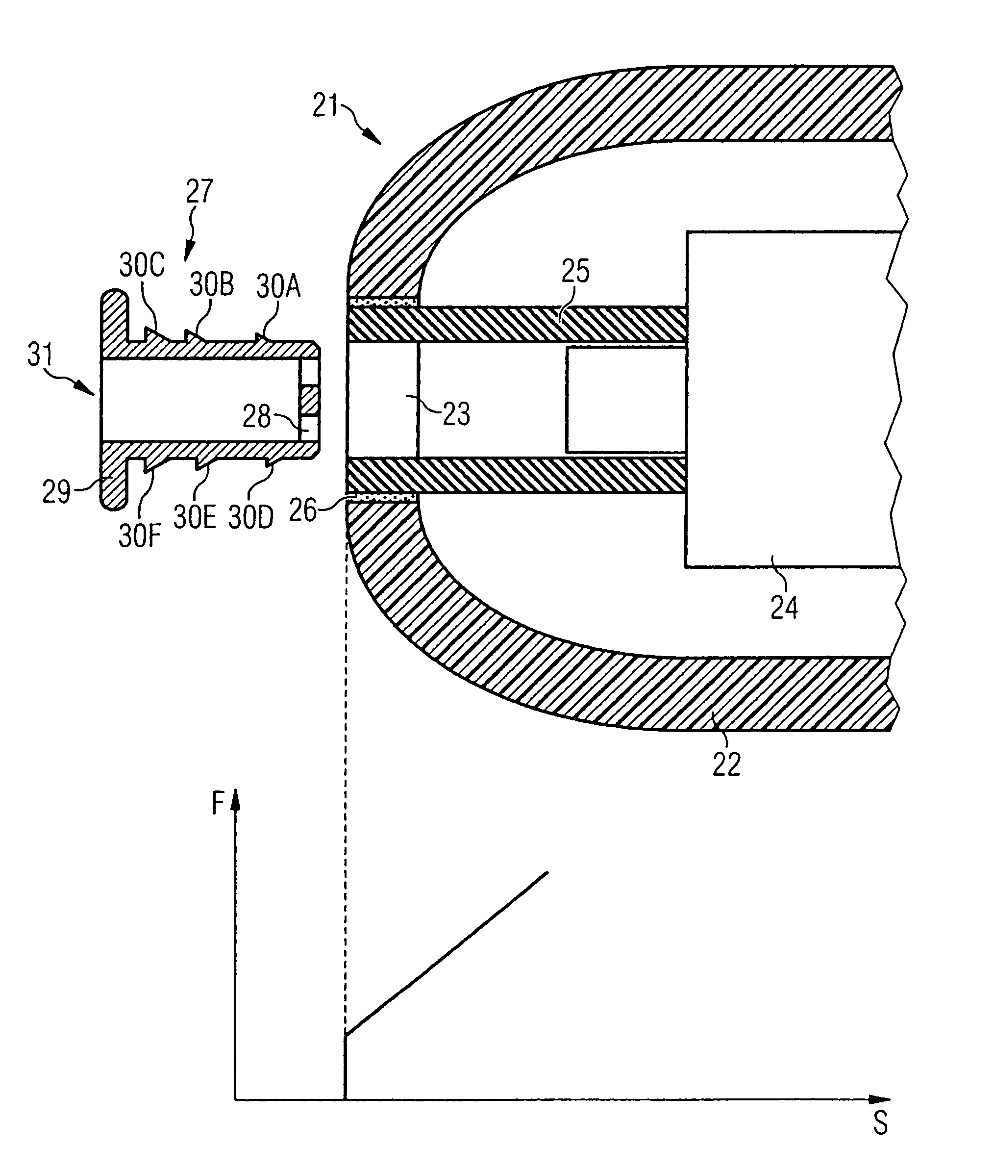
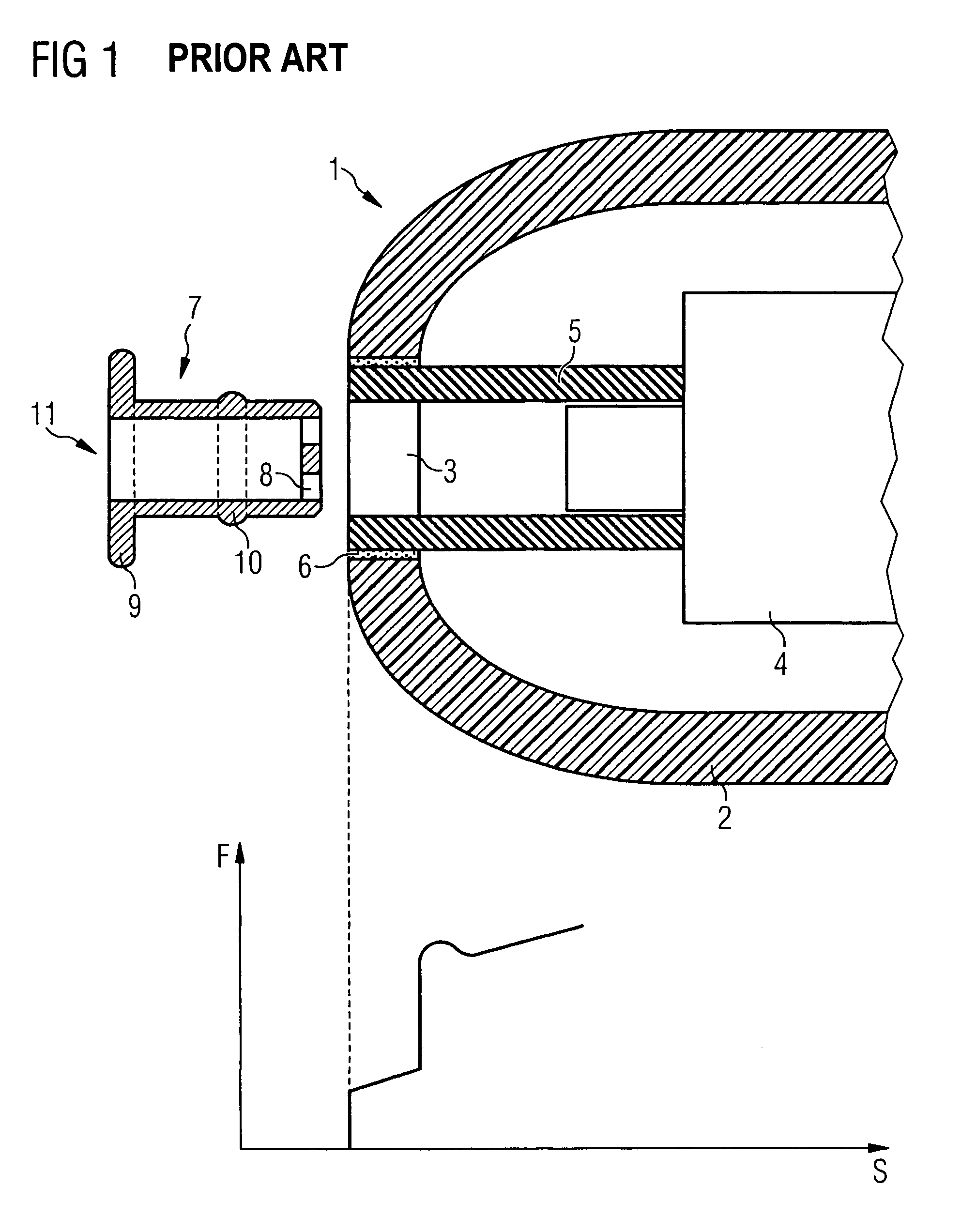
[0020]FIG. 1 shows the front, proximal end of an in-the-ear hearing aid, and an ear wax guard according to the prior art. The in-the-ear hearing aid 1 comprises a housing 2 with a sound outlet opening 3 arranged in the housing. Arranged inside the housing 2 there is a receiver 4 which is connected to the sound outlet opening 3 via a sound tube 5. In the area of the sound outlet opening 3, the sound tube 5 is usually secured on the housing 2 of the hearing aid 1 via a securing mechanism, for example, an adhesive 6.

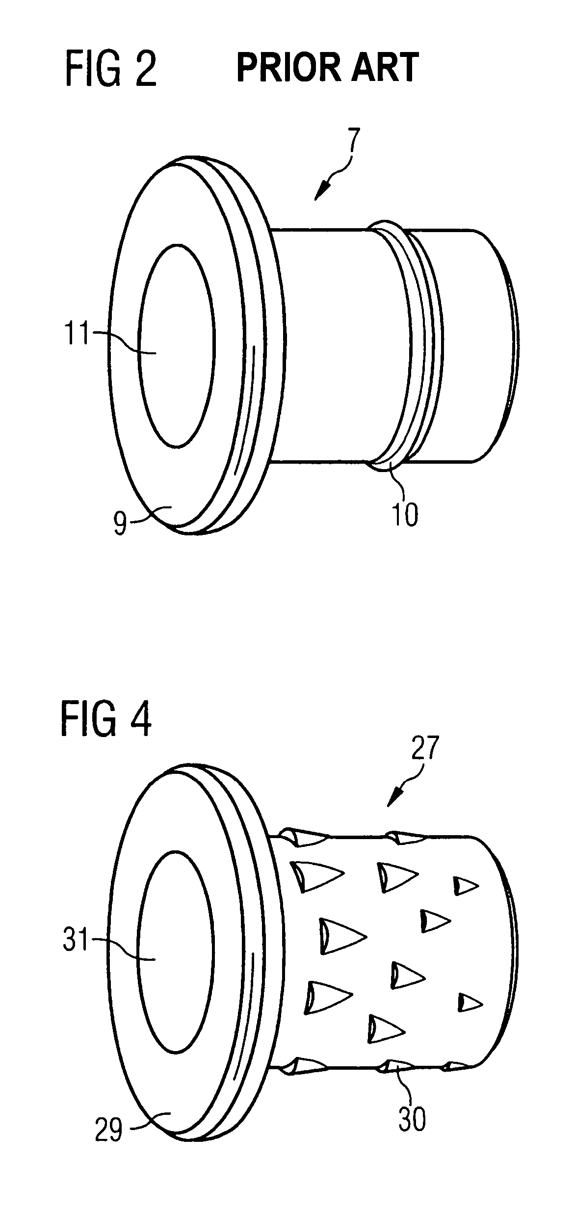
[0021]To protect the hearing aid 1 from soiling, an ear wax guard 7 is provided which can be inserted partially into the sound tube 5. This ear wax guard is of substantially tubular design, so as to be able to conduct the sound from the receiver 4 into the auditory canal of a hearing aid wearer. The external diameter of the tubular ear wax guard 7 corresponds approximately to the internal diameter of the sound tube 5. In order to prevent penetration of wax into the hearing ...


PUM


Abstract

To prevent soiling of a hearing aid, the latter is provided with an exchangeable ear wax guard which, in the area of the sound outlet opening of the hearing aid, can be inserted into a sound tube. The ear wax guard is characterized in that, in order to improve its securing in the sound channel, it is provided with elevations at least in a subarea of its surface. On the surface of the ear wax guard, the density or size of the elevations preferably increases counter to the direction of insertion of the ear wax guard.

Description

BACKGROUND OF THE INVENTION[0001]The invention relates to an ear wax guard for a hearing aid which comprises at least a microphone, an amplifier unit and a receiver, in which sound signals picked up by the microphone are amplified in the amplifier unit, are converted into acoustic signals by the receiver, and are delivered via a sound channel to the eardrum, and in which the ear wax guard can be fitted entirely or partially into the sound channel.[0002]International Patent Publication WO99 / 07182 A2 discloses an acoustic coupler with an ear wax guard. On assembly of the coupler, a receiver is mounted in a housing which is provided with a thread or a toothed surface and in this way can be screwed into the coupler or can be locked in notches of the coupler.[0003]International Patent Publication WO 00 / 03561 discloses an ear wax guard which can be inserted into the sound outlet opening of a hearing aid and can be removed from this again for replacement. The ear wax guard has a substantia...

Claims


Application Information

Patent Timeline
Patent Type & Authority Patents(United States)
IPC IPC(8): H04R25/00
CPCH04R25/654
Inventor WOLF, HERBERT
Owner SIEMENS AUDIOLOGISCHE TECHN
Why Eureka
Try Eureka