Vibration type drive unit

a technology of vibration type and drive unit, which is applied in the direction of piezoelectric/electrostrictive/magnetostrictive devices, piezoelectric/electrostriction/magnetostriction machines, electrical equipment, etc., can solve the problems of increasing the cost of the element in the drive circuit, the miniaturization of the longitudinal direction of the supporting member of the vibration type drive unit not so much as the size in the radial direction of the rotor, and the increase of the cost of th

Inactive Publication Date: 2006-03-21
CANON KK
View PDF7 Cites 7 Cited by
  • Summary
  • Abstract
  • Description
  • Claims
  • Application Information

AI Technical Summary

Benefits of technology

[0020]With these structures, without increasing the natural frequency ...

Problems solved by technology

However, the vibration type drive unit shown in FIGS. 12A and 12B is not suitable for being miniaturized so much due to its shape.
However, as seen in FIGS. 13A and 13B, since the vibrator is constructed in such a way that the piezoelectric element is sandwiched between two elastic bodies, mi...

Method used


Image

  • Vibration type drive unit
  • Vibration type drive unit
  • Vibration type drive unit

Examples


Embodiment Construction

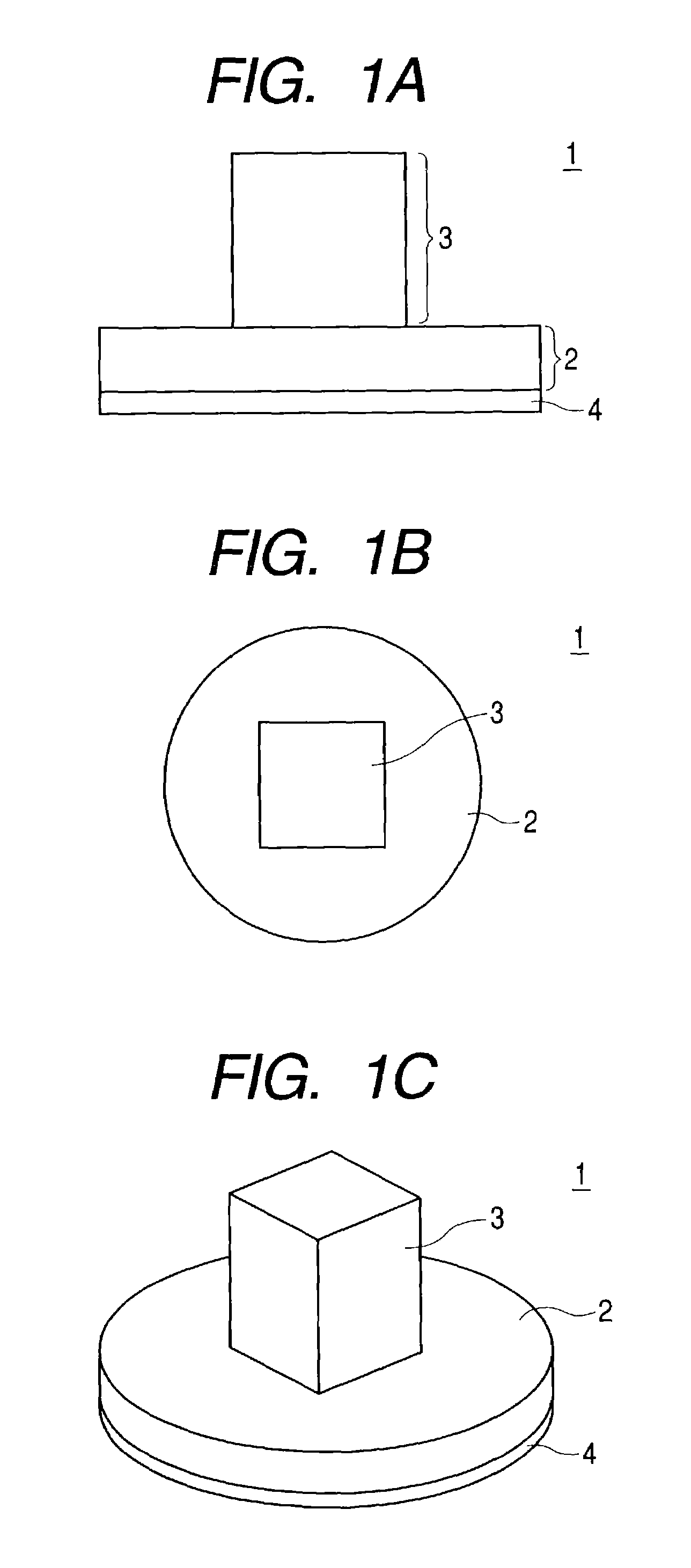
[0035]FIGS. 1A, 1B and 1C show a schematic view of a vibrator constructing a vibration type drive unit according to the present invention.

[0036]In the same drawing, FIG. 1A is a side view of the vibrator, FIG. 1B is a top view in which the vibrator is seen from a direction orthogonal to FIG. 1A, and FIG. 1C is a perspective view of the vibrator.

[0037]The vibrator 1 in FIGS. 1A, 1B and 1C has a structure that a piezoelectric element 4 that is an electromechanical energy conversion element is fixed by gluing or the like to a side surface of a plate-like (disc-like) elastic body 2 made of a material, such as a metal, whose periodic damping loss is small. Other than fixing by gluing, it is possible that through holes are formed in the central portions of the elastic body and piezoelectric element so that a screw inserted into the inner portion of the through hole is engaged with a nut as described later. A column-like elastic body 3 protruding in a direction perpendicular to a fixing su...


PUM


Abstract

A vibration type drive unit comprises a vibrator made of an elastic body to which an electromechanical energy conversion element is fixed and a moving element which is in contact with a surface of the vibrator so that by applying an alternating signal to the electromechanical energy conversion element. A progressive wave is generated on a surface of the vibrator to move the moving element, wherein the vibrator has a plate-like elastic body and a column-like elastic body, the electromechanical energy conversion element is fixed to a side surface of the plate-like elastic body. The column-like elastic body is formed on a central portion of a surface of the plate-like elastic body which is different from the surface to which the electromechanical energy conversion element is fixed.

Description

BACKGROUND OF THE INVENTION[0001]1. Field of the Invention[0002]The present invention relates to a structure of a vibration type drive unit such as an ultrasonic motor and the like and, in particular, to an improvement of the structure of a vibrator whose vibration is excited by applying a signal to a piezoelectric element.[0003]2. Related Background Art[0004]There is a vibration type drive unit, such as an ultrasonic motor and the like, in which a piezoelectric element that is an electromechanical energy conversion element is fixed on an elastic body, for example, made of a metal and an alternating signal is applied to this piezoelectric element to generate a progressive wave on the surface of the elastic body so as to move a moving element (rotor) which is at a pressure contact with the surface of elastic body by the progressive wave.[0005]FIGS. 12A, 12B, 13A and 13B illustrate examples of the formations of conventional vibration type drive units.[0006]FIG. 12A is a perspective vi...

Claims


Application Information

Patent Timeline
IPC IPC(8): H02N2/00H01L41/09H02N2/16
CPCH02N2/16
Inventor NITTO, KIYOSHI
Owner CANON KK
Why Eureka
Try Eureka