Stacker crane

Active Publication Date: 2006-03-28
MURATA MASCH LTD
View PDF11 Cites 2 Cited by
  • Summary
  • Abstract
  • Description
  • Claims
  • Application Information

AI Technical Summary

Benefits of technology

[0005]It is thus an object of the present invention to provide a stacker crane having a frame structure that has an increased rigidity in spite of its compact configuration, the stacker crane allowing articles stocked in an automatic warehouse to be retrieved even if electric power interruption or a failure occurs.
[0006]To attain this object, the present invention uses the means described below. According to an aspect of the invention, there is provided a stacker crane comprising a mast extended vertically from a lower frame and a platform that elevates and lowers along the mast, wherein a ladder is extended vertically at a position opposite to the mast across the platform in a direction in which the lower frame runs, and a top of the mast and a top of the ladder are connected together via an upper frame.

Problems solved by technology

However, increasing the rigidity requires the thickness of the mast to be increased, thus increasing the size of the stacker crane.
Accordingly, if trouble such as electric power interruption occurs, the stacker crane cannot be operated until electric conduction is resumed.
Thus, even if works in process that must be processed urgently are stocked in the automatic warehouse, the urgent works in process cannot be retrieved until the trouble is settled to allow the stacker crane to be restarted.

Method used


Image

  • Stacker crane
  • Stacker crane
  • Stacker crane

Examples


Embodiment Construction

[0022]Embodiments of the present invention will be described with reference to the accompanying drawings.

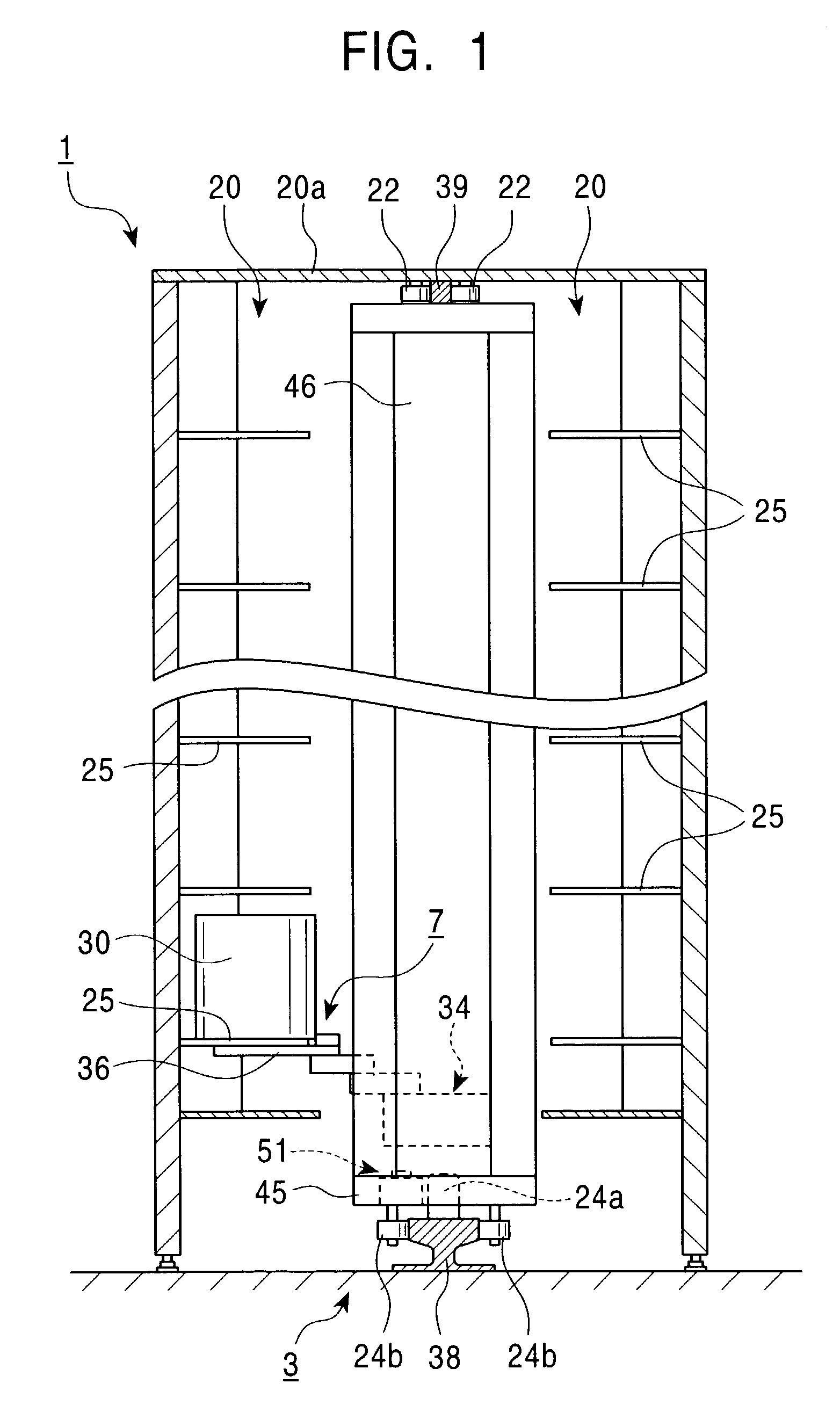
[0023]First, a brief description will be given of the entire configuration of an automatic warehouse comprising a stacker crane according to the present invention.

[0024]An automatic warehouse 1 shown in FIG. 1 comprises a pair of housing sections 20, 20 having a large number of article housing shelves 25 and a stacker crane 3.

[0025]The pair of housing sections 20, 20 are arranged opposite each other across a running rail 38 laid on a floor surface. Each of the housing sections 20 comprises the large number of housing shelves 25 arranged in a longitudinal direction (the direction of a running rail 38) and in a vertical direction.

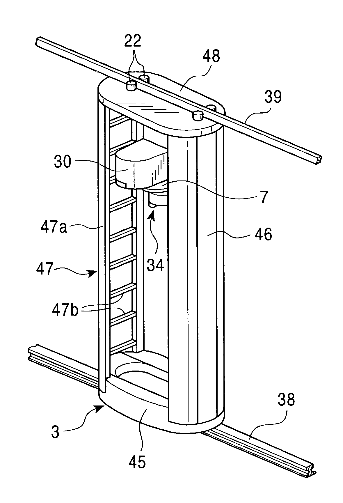
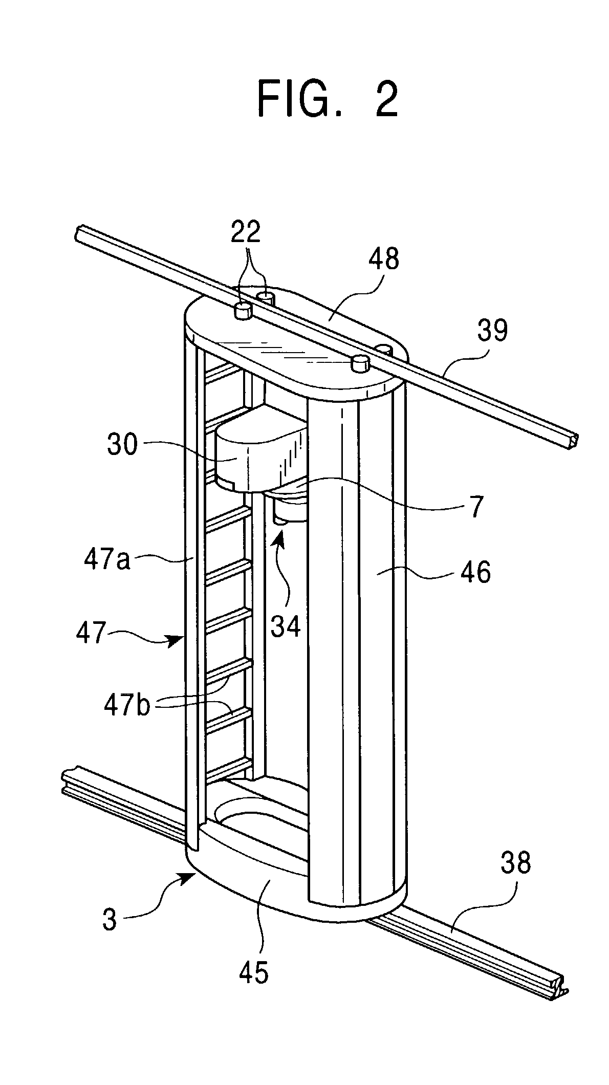
[0026]A lower frame 45 is located at the lower end of the stacker crane 3 to act as a carriage, and is provided with a running wheel 24a running on the running rail 38 and guide wheels 24b, 24b. The running wheel 24a is driven by a running device 51 instal...


PUM


Abstract

A mast in a conventional stacker crane is configured to extend in a vertical direction. Accordingly, the mast is not sufficiently rigid, and may swing in a running direction during running or when the running operation is stopped. An attempt to increase the rigidity results in a thicker mast, thus increasing the size of the stacker crane. In order to solve this problem, a mast is extended vertically from a lower frame and a platform that elevates and lowers along the mast wherein a ladder is extended vertically at a position opposite to the mast across the platform in a direction in which the lower frame runs, and a top of the mast and a top of the ladder is connected together via an upper frame.

Description

FIELD OF THE INVENTION[0001]The present invention relates to the configuration of a stacker crane comprising a mast extended vertically from a lower frame and a platform that elevates and lowers along the mast, the stacker crane automatically running along a running path arranged between a pair of racks.BACKGROUND OF THE INVENTION[0002]A known automatic warehouse for a clean room comprises a pair of racks and a stacker crane automatically running along a running path arranged between the racks. The stacker crane comprises a mast extended vertically from a lower frame and a platform that can elevate and lower along the mast. The stacker crane also has running means and a loading mechanism.[0003]In this stacker crane, the mast, which supports the platform, is configured to extend in a vertical direction. Accordingly, if the mast has an insufficient rigidity, it may be swung in the running direction during running or when the running operation is stopped. To hinder this swing, the fram...

Claims


Application Information

Patent Timeline
IPC IPC(8): B65G1/04B66F9/07
CPCB66F9/07
Inventor TAI, AKITO
Owner MURATA MASCH LTD
Why Eureka
Try Eureka