
Protective cover system for painting applications

Inactive Publication Date: 2006-04-04
ATO ERNESPRISE
View PDF6 Cites 26 Cited by
  • Summary
  • Abstract
  • Description
  • Claims
  • Application Information

AI Technical Summary

Benefits of technology

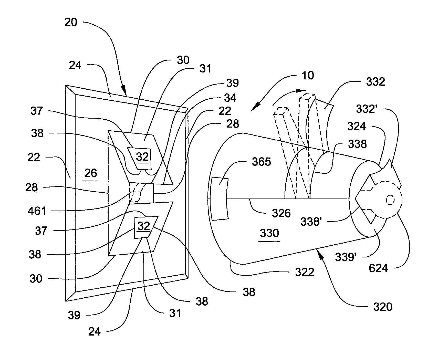
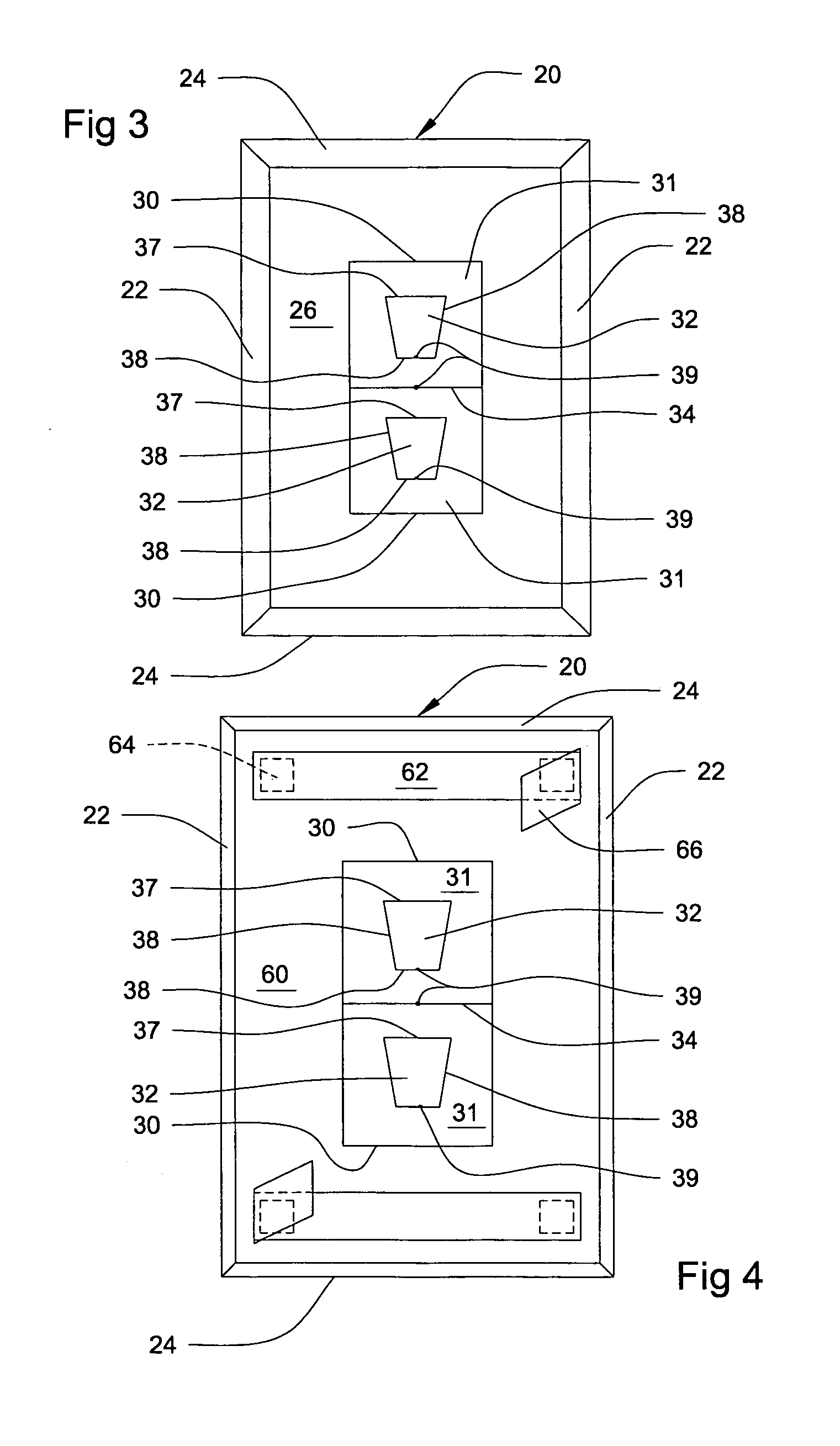
[0010]A removable cover system to prevent application of paint on cover plates and doorknobs, comprising a cover plate cover assembly comprising a first outwardly facing surface and a first inwardly facing surface. The first outwardly facing surface has first and second edges parallel and equally spaced apart from each other by third and fourth edges. The first outwardly facing surface is smooth to effectively repel paint. The cover plate cover assembly also comprises longitudinal lines that are parallel and equally spaced apart from each other by a horizontal borderline, to define first surfaces. The first surfaces may be lifted outwardly from the horizontal borderline at first hinges to facilitate mounting of the cover plate cover assembly upon a cover plate to use at least one switch. The first surfaces comprise second surfaces that may be lifted outwardly along first perforations at second hinges to facilitate mounting of the cover plate cover assembly upon the cover plate to use at least one receptacle. The first inwardly facing surface is matte and porous to effectively adhere to the cover plate. The first inwardly facing surface comprises at least one adhesive tab with wax paper. The wax paper has at least one corner tab to facilitate a user in removing the wax paper from the at least one adhesive tab. The at least one adhesive tab has first adhesive means to keep the cover plate cover assembly securely adhered to the cover plate.
[0016]It is therefore one of the main objects of the present invention to provide a removable protective cover system for painting applications to prevent application of paint on cover plates and doorknobs, for electronic outlets and switches, and door handles respectively.
[0017]It is yet another object of this invention to provide such a system that is inexpensive to manufacture and maintain while retaining its effectiveness.

Problems solved by technology

Painting is a time consuming task.
And preparing a room for painting also takes time.
However, this is a cumbersome task and eventually the cover plates and doorknobs will be replaced.
In addition, removing cover plates leaves outlets exposed that may be dangerous, and removing door handles may make doors unusable.
None of them, however, includes cover plate cover and doorknob cover assemblies to prevent application of paint on cover plate and doorknob assemblies, for electronic outlets and switches, and door handles respectively.

Method used


Image

  • Protective cover system for painting applications
  • Protective cover system for painting applications
  • Protective cover system for painting applications

Examples


Embodiment Construction

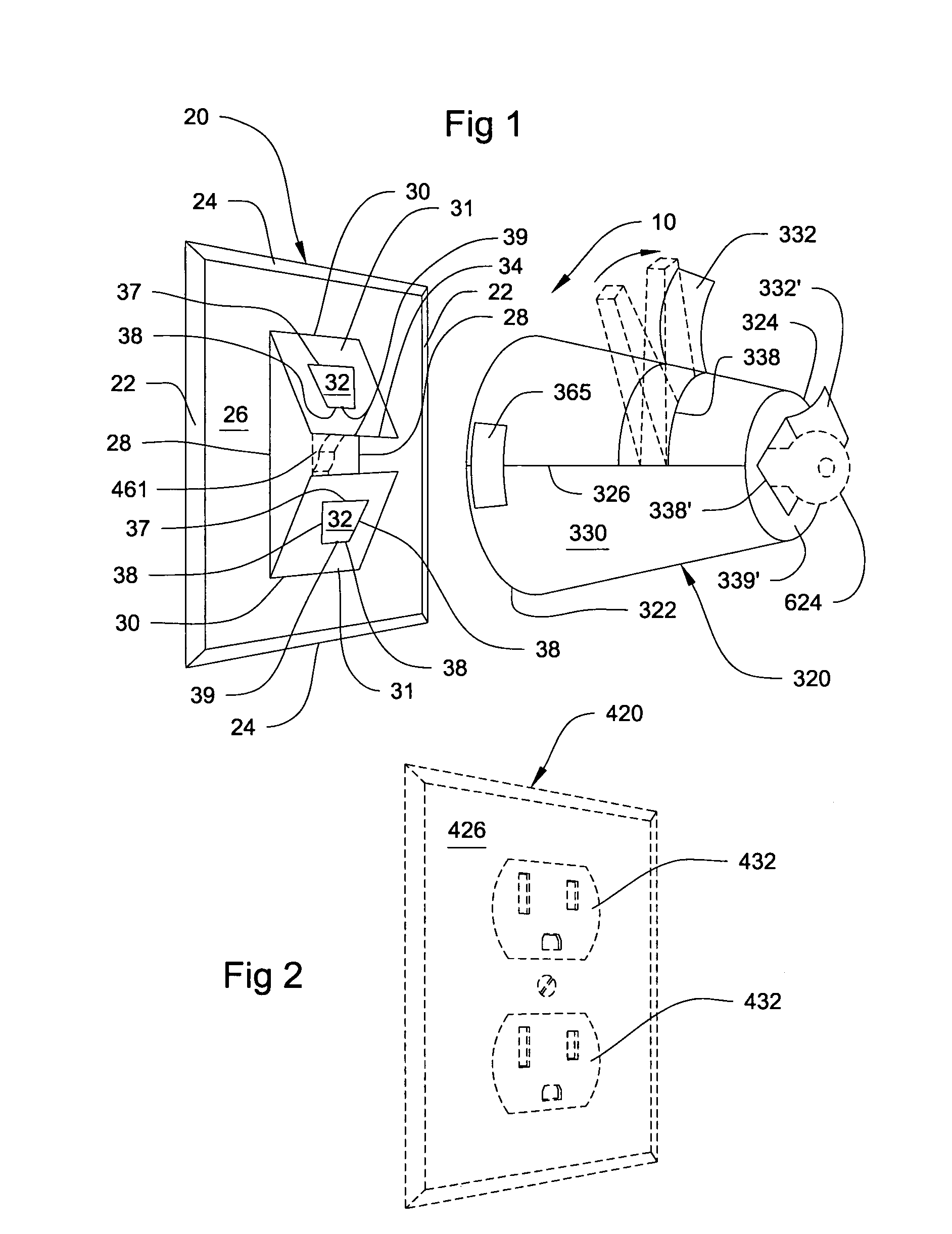
[0028]Referring now to the drawings, where the present invention is generally referred to with numeral 10, it can be observed that it basically includes cover plate cover assembly 20 and doorknob cover assembly 320.

[0029]As seen in FIG. 1, cover plate cover assembly 20 comprises outwardly facing surface 26 having edges 22 parallel and equally spaced apart from each other by edges 24. Outwardly facing surface 26 is smooth to effectively repel paint. Longitudinal lines 28 are parallel and equally spaced apart from each other by horizontal border line 34, all of which form a H-shaped die-cut that define surfaces 31. Surfaces 31 may be lifted outwardly from horizontal border line 34 at hinges 30, to facilitate the mounting of cover plate cover assembly 20 upon typical prior art cover plate having a switch, such as switch 461. Surfaces 32 may be lifted outwardly along their respective perforations 38 at hinges 37, to facilitate the mounting of cover plate cover assembly 20 upon typical p...


PUM


Abstract

A removable protective cover system to prevent application of paint on cover plates having electronic outlets and switches, and doorknobs having door handles. The system includes a cover plate cover assembly, and a doorknob cover assembly that is conical in shape.

Description

BACKGROUND OF THE INVENTION[0001]1. Field of the Invention[0002]The present invention relates to a system for masking or covering surfaces of articles, to prevent paint or other surfaces from coming in contact with these as protected surfaces and more particularly, to protective covers used to prevent application of paint on cover plates and doorknobs, for electronic outlets and switches, and door handles respectively.[0003]2. Description of the Related Art[0004]Painting is a time consuming task. And preparing a room for painting also takes time. In some cases, a person will remove cover plates and doorknobs to ensure that paint is not applied to them. However, this is a cumbersome task and eventually the cover plates and doorknobs will be replaced. In addition, removing cover plates leaves outlets exposed that may be dangerous, and removing door handles may make doors unusable. There is a need for a protective cover system for masking or covering surfaces of articles, to prevent pa...

Claims


Application Information

Patent Timeline
IPC IPC(8): H02G3/14
CPCH02G3/14B05B15/045B05B12/20
Inventor GALGUERA, ERNESTO
Owner ATO ERNESPRISE
Learn More