Video encoding apparatus and method

Inactive Publication Date: 2006-04-04
KK TOSHIBA
View PDF6 Cites 141 Cited by
  • Summary
  • Abstract
  • Description
  • Claims
  • Application Information

AI Technical Summary

Benefits of technology

[0010]It is an object of the present invention to provide a video encoding apparatus and method that can execute efficient bi

Problems solved by technology

Consequently, in scenes having significant motions within the screen, the frame interval increases excessively to make the motions unnatural or an inappropriate quantization step size contributes to distorting the video, resulting in a failure to provide viewers an easy-to-see video.
As described above, in the conventional video encodin

Method used


Image

  • Video encoding apparatus and method
  • Video encoding apparatus and method
  • Video encoding apparatus and method

Examples


Embodiment Construction

[0028]Embodiments of the present invention will be described below with reference to the drawings.

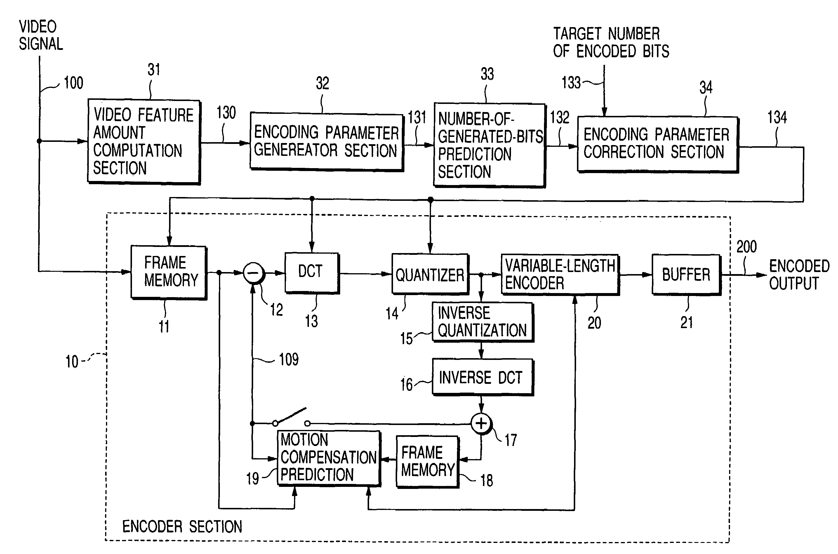
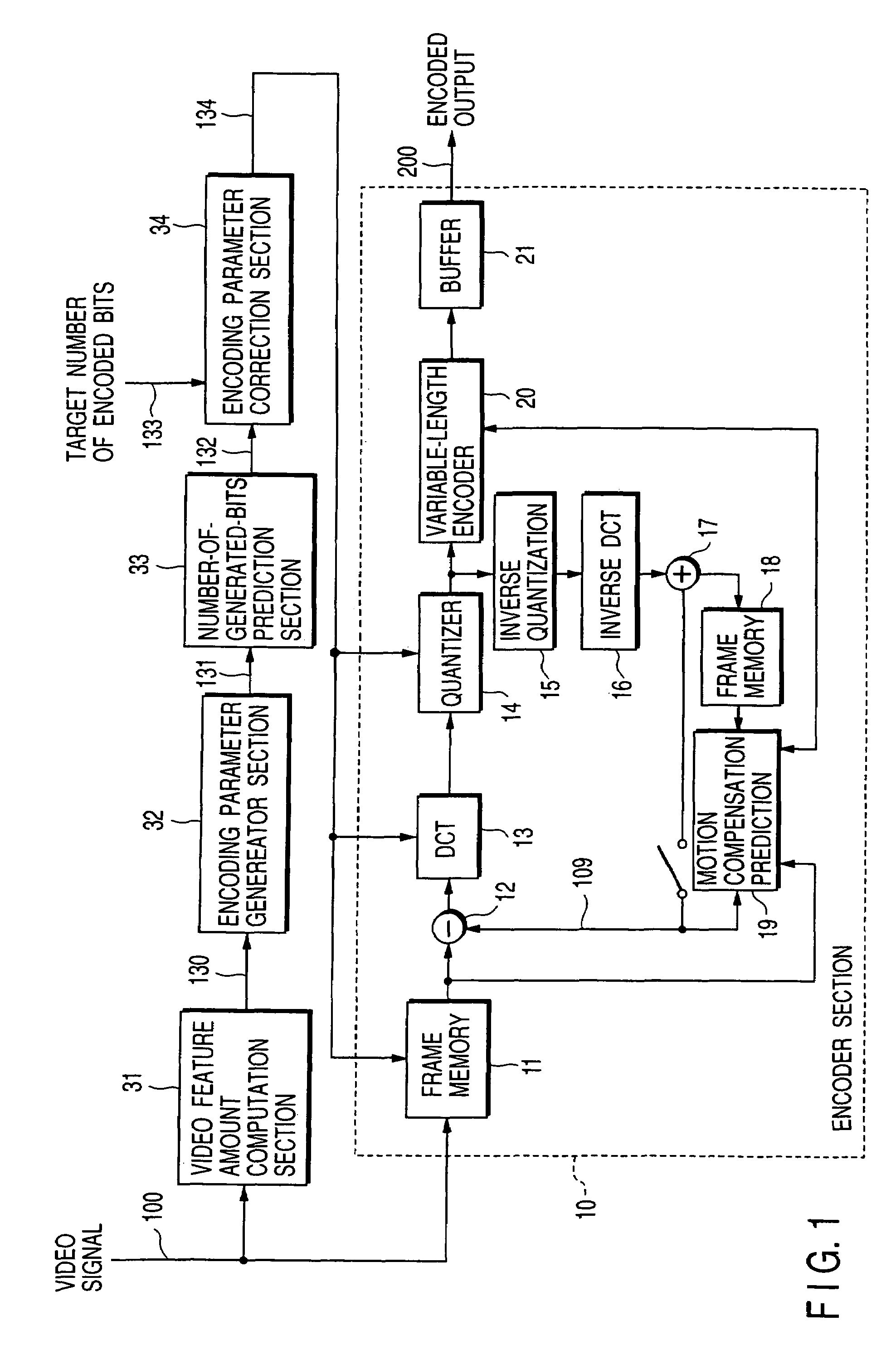
[0029]FIG. 1 is a block diagram showing the configuration of a video encoding apparatus according to one embodiment of the present invention. An input video signal 100 is reproduced by a video recording and reproducing apparatus such as a digital VTR or a DVD system which can repeat reproducing the same signal a number of times and is input to a video feature computation section 31 and a frame memory 11 of an encoder section 10.

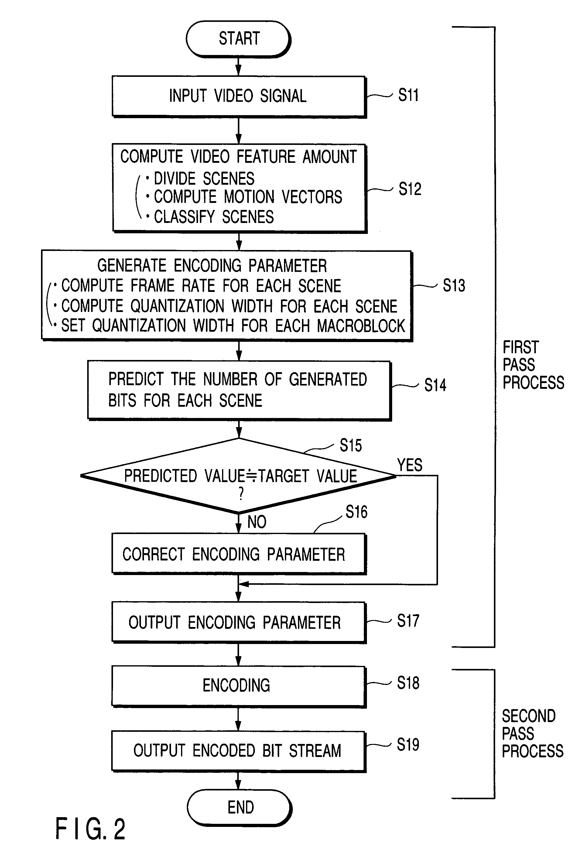
[0030]It is well known that motion compensation adaptive prediction, discrete cosine transformation, and quantization are used for the MPEG encoding. A two-pass encoding process will be described below.

[0031]In an encoding apparatus shown in FIG. 1, a video signal 100 is input to the video feature computation section 31 before the frame memory 100, an encoding parameter is calculated (first pass), and the calculated encoding parameter 134 and the video signal 100...


PUM


Abstract

A video encoding apparatus comprising a feature amount computation section which divides an input video signal into a plurality of scenes each comprising at least one temporally-continuous frame, and compute a statistical feature amount for each scene, an encoding parameter generator section which generates an encoding parameter for each scene based on the statistical feature amount, a number-of-generated-bits prediction section which predicts the number of bits to be generated when the input video signal is encoded using the encoding parameter, an encoding parameter correcting section which corrects the encoding parameter based on a result of the prediction of the number of generated bits, an encoder section which encodes the input video signal using the corrected encoding parameter.

Description

CROSS-REFERENCE TO RELATED APPLICATIONS[0001]This application is based upon and claims the benefit of priority from the prior Japanese Patent Application No. 2000-053823, filed Feb. 29, 2000, the entire contents of which are incorporated herein by reference.BACKGROUND OF THE INVENTION[0002]The present invention relates to a vide encoding apparatus and method for use in a video transmission system or a video data system using the Internet, and in particular, to a video encoding apparatus and method that can use a two-pass encoding method to carry out encoding using encoding parameters depending on the contents of scenes, to provide an easy-to-see decoded video that is coordinated for each scene without the need to increase a data size.[0003]The MPEG method used to compress a video compresses data by subjecting error signals in motion compensation between frames of video data to discrete cosine transform (DCT) and quantizing relevant coefficients.[0004]A conventional video encoding me...

Claims


Application Information

Patent Timeline
IPC IPC(8): H04N7/18H04N5/92G06T9/00H03M7/30H04N19/105H04N19/119H04N19/126H04N19/13H04N19/134H04N19/139H04N19/149H04N19/159H04N19/167H04N19/172H04N19/176H04N19/189H04N19/192H04N19/194H04N19/196H04N19/50H04N19/503H04N19/51H04N19/527H04N19/547H04N19/61H04N19/625H04N19/86H04N19/91H04N19/94
CPCH04N19/139H04N19/172H04N19/51H04N19/196H04N19/15H04N19/194H04N19/60H04N19/126H04N19/14H04N19/179H04N19/192H04N19/61
Inventor FURUKAWA, RIEKOKIKUCHI, YOSHIHIRO
Owner KK TOSHIBA
Why Eureka
Try Eureka