
Method for coding motion vector using 2-dimensional minimum bitrate predicting technique

Inactive Publication Date: 2006-04-04
LG ELECTRONICS INC
View PDF5 Cites 42 Cited by
  • Summary
  • Abstract
  • Description
  • Claims
  • Application Information

AI Technical Summary

Benefits of technology

[0026]Therefore, an object of the present invention is to provide a method for improving a coding efficiency of a motion vector by transmitting prediction error information (MVD) and mode information (MODE) by using a two-dimensional minimum bitrate predicting technique.
[0027]Another object of the present invention is to provide a method for heightening a coding efficiency by two-dimensionally coding prediction error information generated due to a minimum bitrate predicting technique.
[0028]Still another object of the present invention is to provide a method for effectively coding mode information (MODE) which is commonly adopted to factors ‘X’ and ‘Y’ by using a two-dimensional minimum bitrate predicting technique.
[0029]Yet another object of the present invention is to provide a method for coding two-dimensional prediction error information for a mobile image of a low transfer rate in a small size and with a little motion.

Problems solved by technology

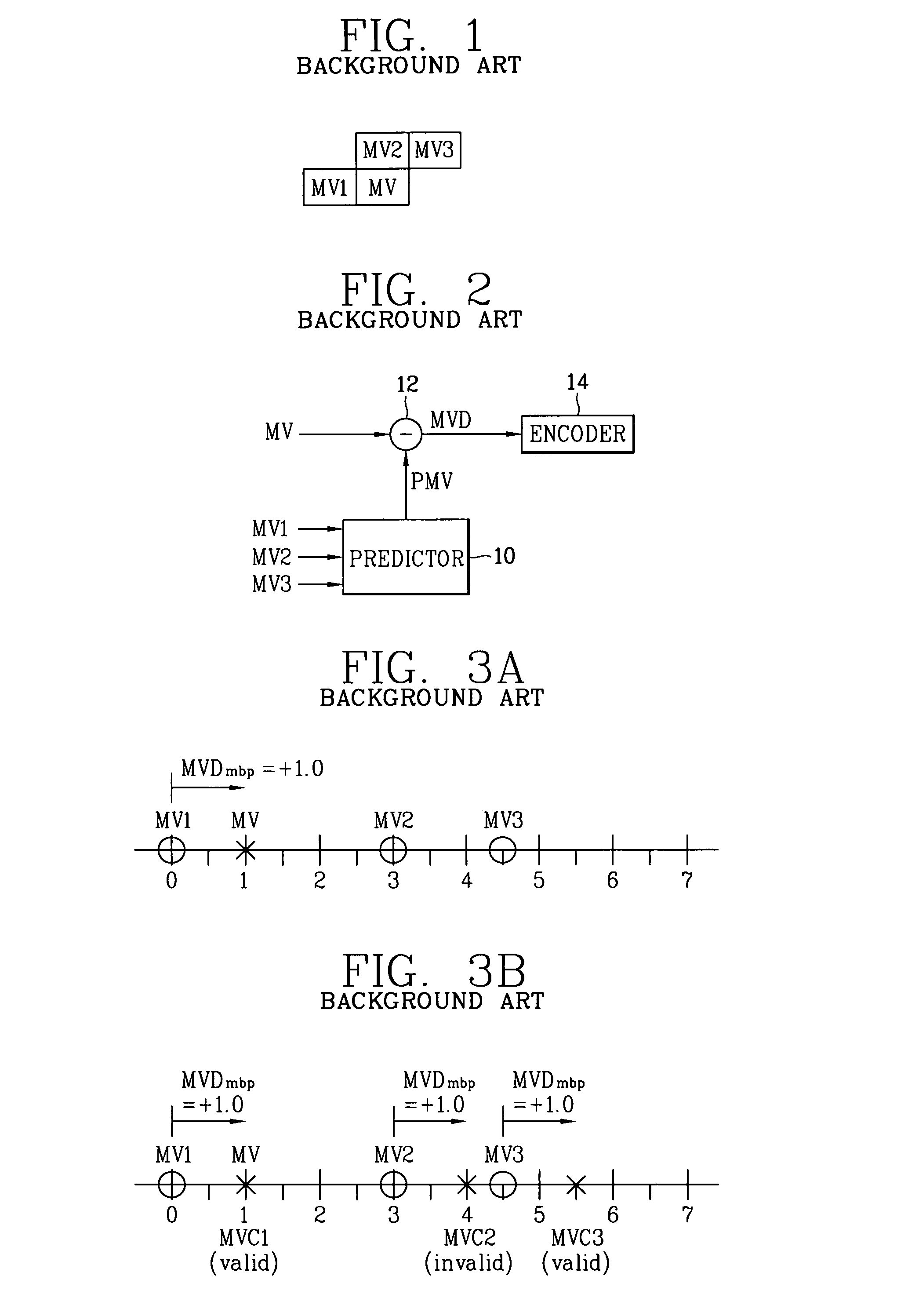
However, the conventional motion vector coding method using the Median predicting technique and the one-dimensional minimum bitrate predicting technique has a problem that since the factors ‘X’ and ‘Y’ of the motion vector are independently processed, causing a disturbance to a real time compression coding and an increase in the amount of the transmitted data,
Especially, in case of the motion vector coding method using the one-dimensional minimum bitrate predicting technique, since the factors ‘X’ and ‘Y’ exist also in the mode information as well as in the prediction error information, transmission burden of the mode information is much increased.
But the conventional motion vector coding method fails to provide a solution which may allow to effectively use a distribution characteristic change of the prediction error (MVD) generated due to the prediction technique.

Method used


Image

  • Method for coding motion vector using 2-dimensional minimum bitrate predicting technique
  • Method for coding motion vector using 2-dimensional minimum bitrate predicting technique
  • Method for coding motion vector using 2-dimensional minimum bitrate predicting technique

Examples


Embodiment Construction

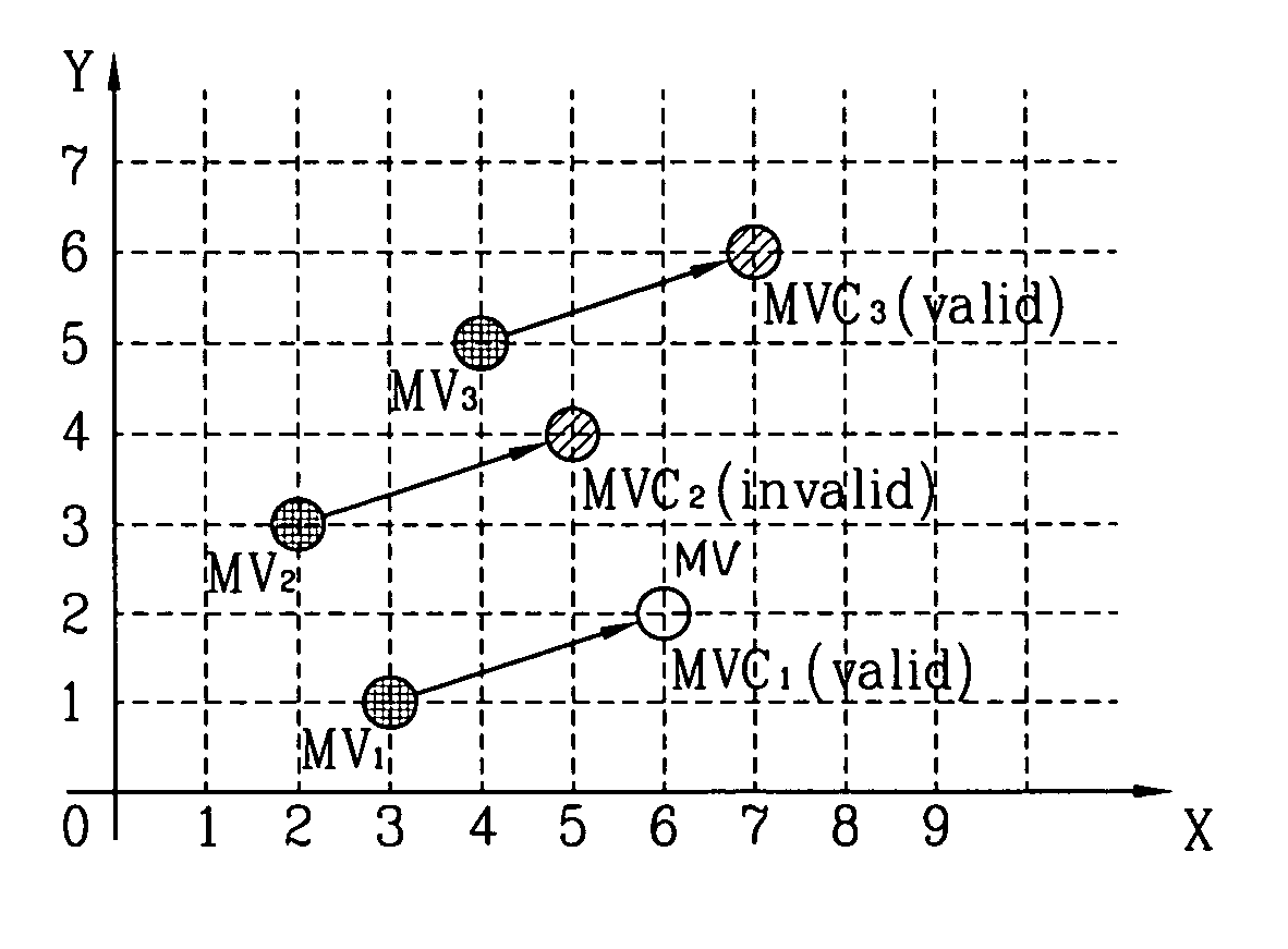
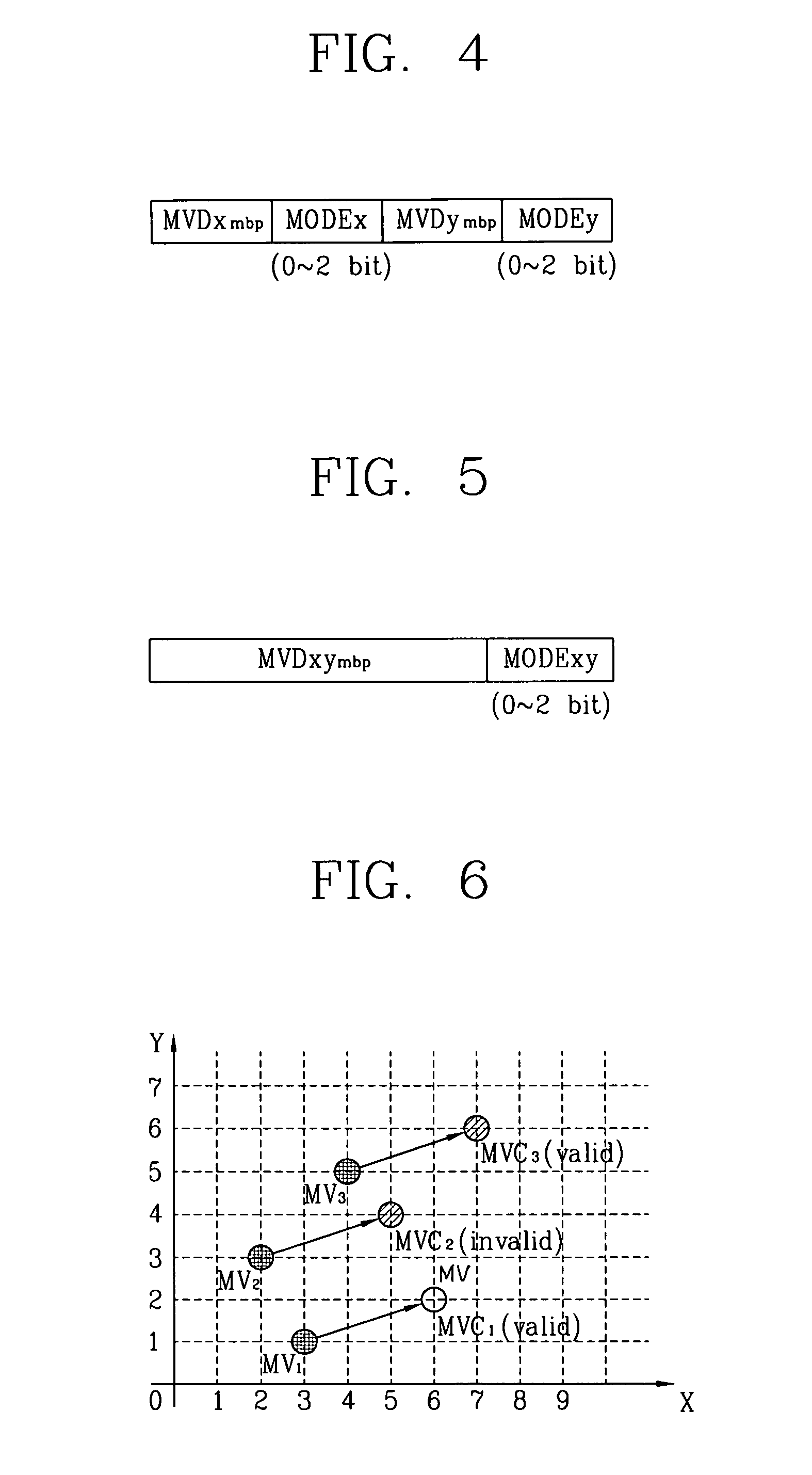
[0043]The present invention presents a method for transmitting prediction error information (MVD) and mode information (MODE) commonly adopted to factors ‘X’ and ‘Y’ through a two-dimensional minimum bitrate predicting technique.

[0044]In general, a vector nearest to a motion vector to be coded among neighboring motion vectors has a high possibility of having the smallest distance to the motion vector to be coded in the aspect of the factors of ‘X’ and ‘Y’.

[0045]Thus, the present invention proposes a method for improving a coding efficiency of a motion vector by reducing a load of the mode information (MODE) while, though, having a bit increased prediction error (MVD) information, through a two-dimensional access method.

[0046]In addition, the present invention proposes a method for two-dimensionally coding MVD information by using a characteristic that a prediction error generated due to a minimum bitrate predicting technique is more converged to (0,0) compared to a prediction error ...


PUM


Abstract

A method for coding a motion vector using a 2-dimensional minimum bitrate predicting technique is disclosed. A mode information (MODE) commonly adopted to the factors ‘X’ and ‘Y’ are transmitted to thereby reduce its transmission burden by using the two-dimensional minimum bitrate predicting technique, so that a coding efficiency of a motion vector can be improved. In addition, the two-dimensional MVD information coding method is proposed for the low transfer rate mobile image which is very small and has very small motion, so that even if a distribution characteristic of the MVD information is changed according to the minimum bitrate prediction, a coding efficiency of a major motion vector can be improved.

Description

BACKGROUND OF THE INVENTION[0001]1. Field of the Invention[0002]The present invention relates to a coding method of a motion vector, and more particularly, to a method for coding a motion vector using a 2-dimensional minimum bitrate predicting technique.[0003]2. Description of the Background Art[0004]In general, a motion vector is coded by a lossless coding in a mobile image compression. In such a case, a differential pulse code modulation (DPCM) technique is mostly used which is divided by a portion for computing a prediction value of a motion vector to be currently coded and a portion for coding a prediction error between the computed prediction value and the current motion vector.[0005]Accordingly, a mobile image compression performance depends on how successfully the current motion vector is predicted by using a neighboring motion vector which has been already transmitted.[0006]Conventional motion vector coding method roughly includes a Median predicting technique and one-dimens...

Claims


Application Information

Patent Timeline
IPC IPC(8): H04N7/12H04N7/32G06T9/00H04N5/14H04N7/26H04N7/36
CPCH04N19/517H04N19/51H04N5/145H04N19/137H04N19/513H04N19/61
Inventor CHO, HYUN DUKKIM, SUNG DEUK
Owner LG ELECTRONICS INC
Learn More