
Battery conducting device for motorized scooter

a technology of conducting device and battery, which is applied in the direction of coupling device connection, electrical apparatus, connection, etc., can solve the problems of inconvenient use and interrupt the electric power supplied by the battery, and achieve the effect of reducing shock or vibration

Inactive Publication Date: 2006-04-11
CHIEN TI ENTERPRISE
View PDF11 Cites 20 Cited by
  • Summary
  • Abstract
  • Description
  • Claims
  • Application Information

AI Technical Summary

Benefits of technology

[0007]The primary objective of the present invention is to provide a battery conducting device having a constantly conducting function without incurring power supply interruption due to a shock or vibration.
[0008]Another objective of the present invention is to provide a battery conducting device, wherein the flat plate of the bolt is connected to the electrode contact member constantly, so that the bolt is connected to the battery constantly, thereby connecting the battery to the motor power supply input successively so as to supply an electric power to the motorized scooter successively without interruption due to a shock or vibration.
[0009]A further objective of the present invention is to provide a battery conducting device, wherein the compression spring mounted on the bolt provides a shock-absorbing function to reduce the shock or vibration applied on the motorized scooter.

Problems solved by technology

However, it is necessary to unscrew and screw the screws when replacing the battery, thereby causing inconvenience to the user.
However, the detachable bonding strap cannot fasten the battery on the vehicle body closely, so that the battery is easily detached from the vehicle body due to a shock or vibration, thereby interrupting the electric power supplied by the battery.

Method used


Image

  • Battery conducting device for motorized scooter
  • Battery conducting device for motorized scooter
  • Battery conducting device for motorized scooter

Examples


Embodiment Construction

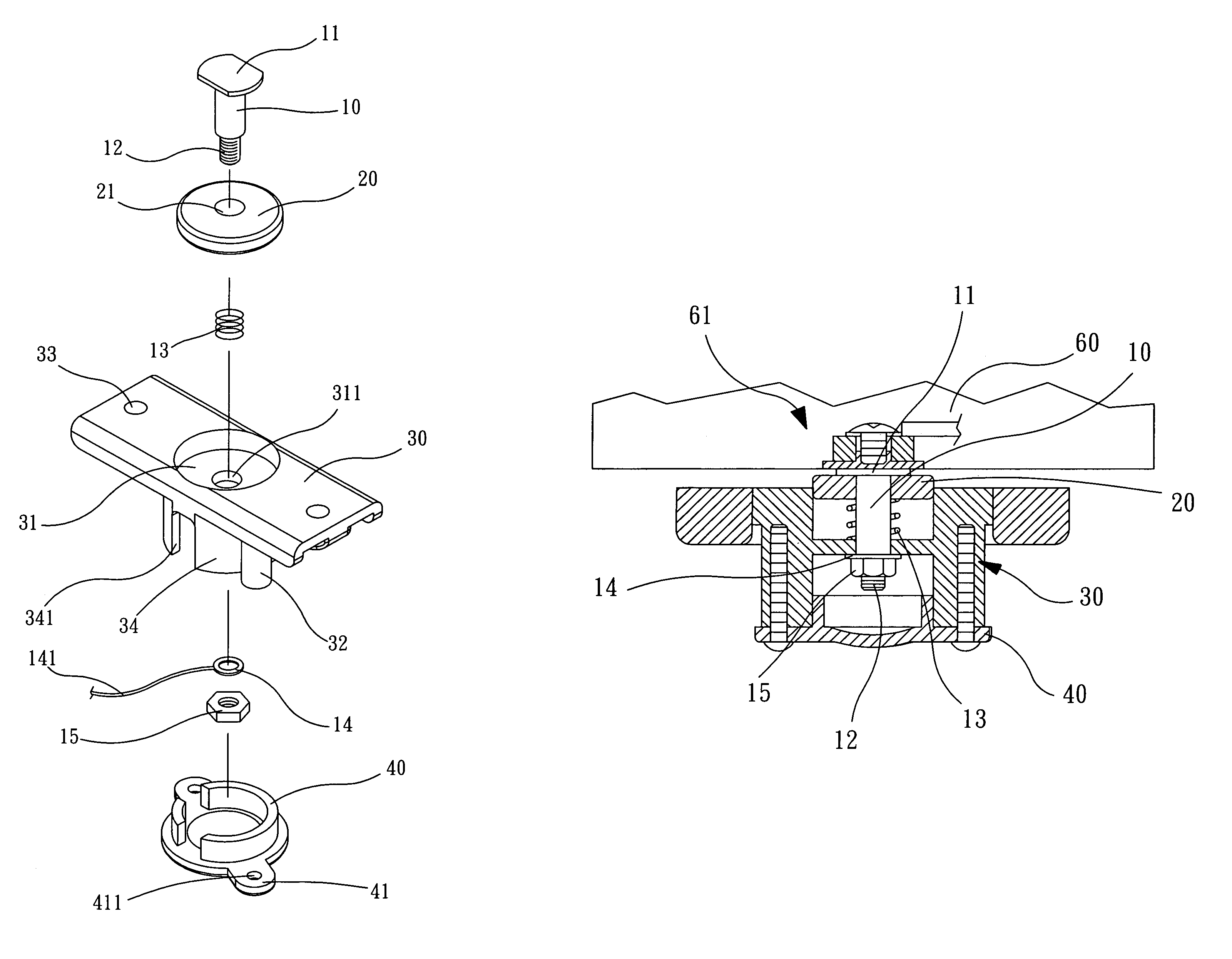
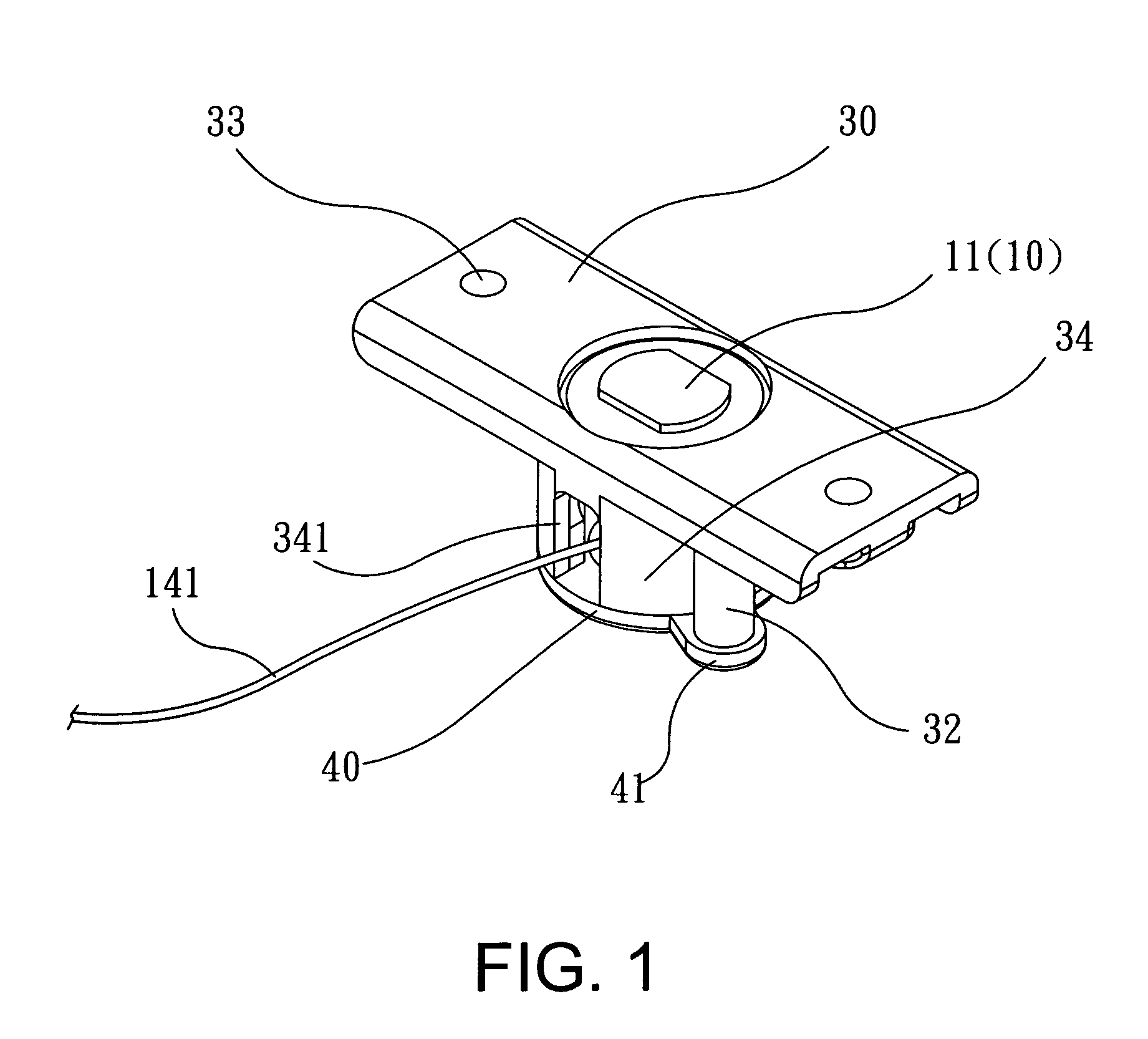
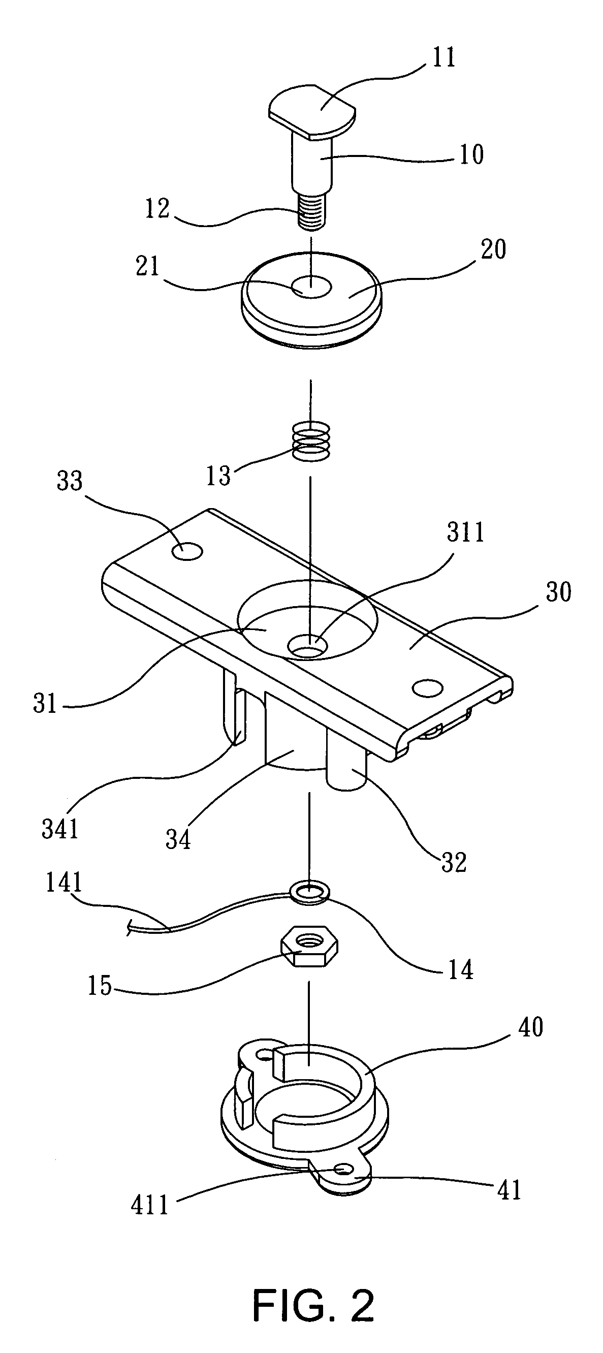
[0017]Referring to the drawings and initially to FIGS. 1–3, a battery conducting device for a motorized scooter in accordance with the preferred embodiment of the present invention comprises a fixing seat 30, a permanent magnet 20, a bolt 10, a cover 40, and an electrode contact member 61.

[0018]The fixing seat 30 is a substantially sheet plate and has a first side formed with a chamber 31 having a face formed with a through hole 311 and a second side formed with a substantially cylindrical peripheral wall 34 having a side formed with an opening 341. The peripheral wall 34 of the fixing seat 30 has an outside formed with two radially opposite threaded posts 32. The fixing seat 30 has two ends each formed with a fixing hole 33.

[0019]The permanent magnet 20 is an annular magnet having a relatively stronger magnetically attractive force. The permanent magnet 20 is movably mounted in the chamber 31 of the fixing seat 30 and has an inside formed with a through hole 21.

[0020]The bolt 10 is...


PUM


Abstract

A battery conducting device for a motorized scooter includes a fixing seat, a permanent magnet movably mounted in the chamber of the fixing seat, a bolt movably mounted on the fixing seat and having a flat plate rested on the permanent magnet, and an electrode contact member rested on the flat plate and attracted by the permanent magnet so that the electrode contact member is bonded on the flat plate closely. Thus, the flat plate is connected to the electrode contact member constantly, so that the bolt is connected to the battery constantly, thereby connecting the battery to the motor power supply input successively so as to supply an electric power to the motorized scooter successively without interruption due to a shock or vibration.

Description

BACKGROUND OF THE INVENTION[0001]1. Field of the Invention[0002]The present invention relates to a battery conducting device, and more particularly to a battery conducting device for a motorized scooter.[0003]2. Description of the Related Art[0004]A conventional motorized scooter comprises a vehicle body, a frame mounted on the vehicle body, and a battery mounted on the frame by a plurality of screws. However, it is necessary to unscrew and screw the screws when replacing the battery, thereby causing inconvenience to the user.[0005]Another conventional motorized scooter comprises a vehicle body, a battery mounted on the vehicle body, and at least one detachable bonding strap mounted between the battery and the vehicle body to secure the battery on the vehicle body. However, the detachable bonding strap cannot fasten the battery on the vehicle body closely, so that the battery is easily detached from the vehicle body due to a shock or vibration, thereby interrupting the electric powe...

Claims


Application Information

Patent Timeline
IPC IPC(8): H01R11/30
CPCH01R11/287H01R13/6205H01R11/30
Inventor CHANG, FENG-CHU
Owner CHIEN TI ENTERPRISE
Learn More