Dynamic ring classifier for a coal pulverizer

a technology of rotary coal pulverizer and ring classifier, which is applied in the direction of centrifuges, solid separation, strainers, etc., can solve the problems of increasing the difficulty of maintaining a consistent rejector arm gap, and the difficulty of installing and maintaining the rejector arm gap at the desired siz

Active Publication Date: 2006-04-18
RILEY STOKER
View PDF8 Cites 23 Cited by
  • Summary
  • Abstract
  • Description
  • Claims
  • Application Information

AI Technical Summary

Problems solved by technology

In these rejector assemblies, it is often difficult to install and maintain the rejector arm gap at the desired size.
Furthermore, wear and tear on the assembly can further increase the difficulty of maintaining a consistent rejector arm gap.

Method used


Image

  • Dynamic ring classifier for a coal pulverizer
  • Dynamic ring classifier for a coal pulverizer
  • Dynamic ring classifier for a coal pulverizer

Examples


Embodiment Construction

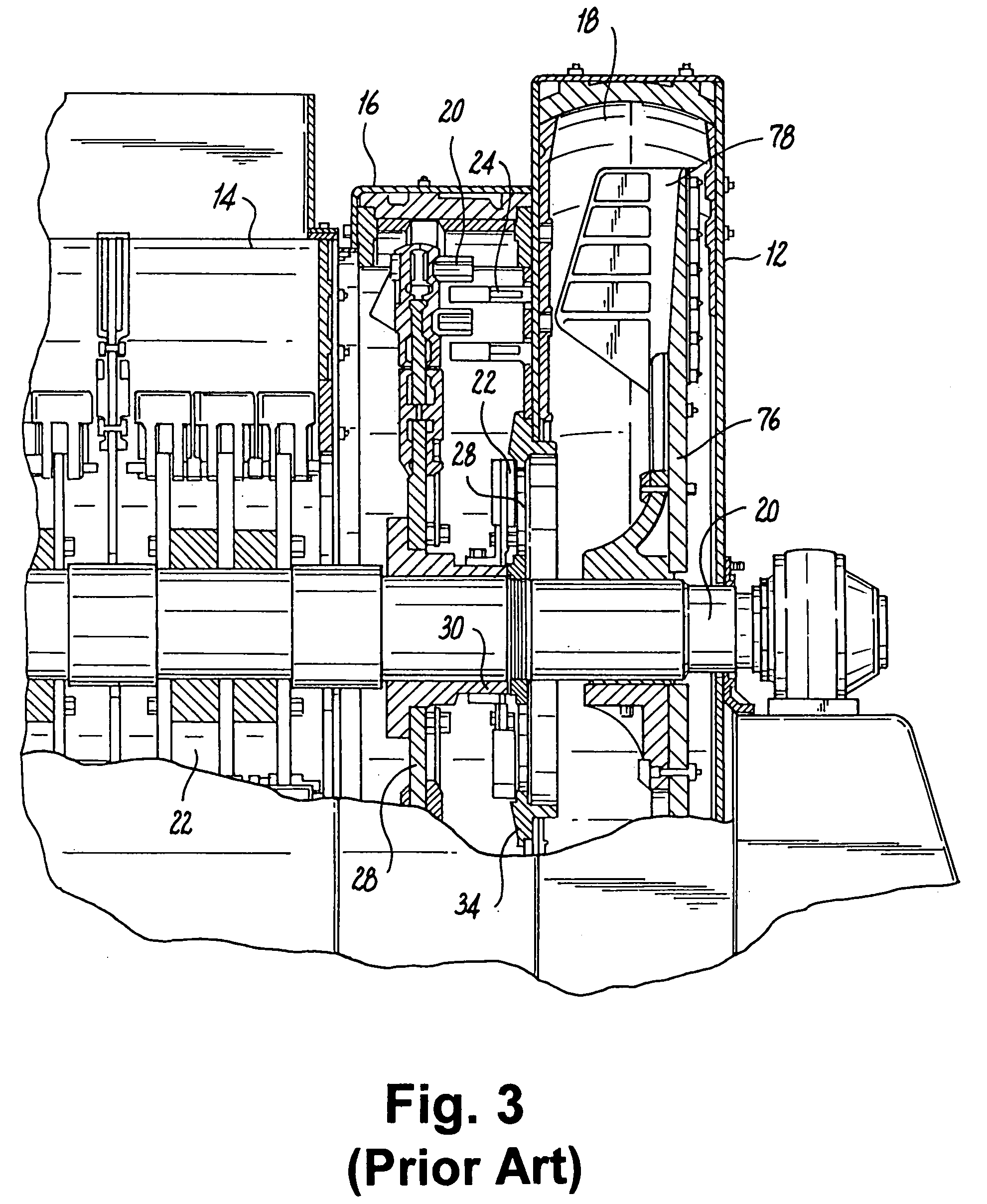
[0025]Reference is now made to the figures and accompanying detailed description which have been provided to illustrate exemplary embodiments of the present invention, but are not intended to limit the scope of embodiments of the present invention. Although a particular type of rotary coal pulverizer is shown in the figures and discussed herein, it should be readily apparent that a device or system constructed in accordance with the present invention can be employed in a variety of other coal pulverizers, or other applications that do not involve coal as the raw material. In other words, the specific material and size reduction process is not vital to gaining the benefits associated with using a system constructed in accordance with the present invention.

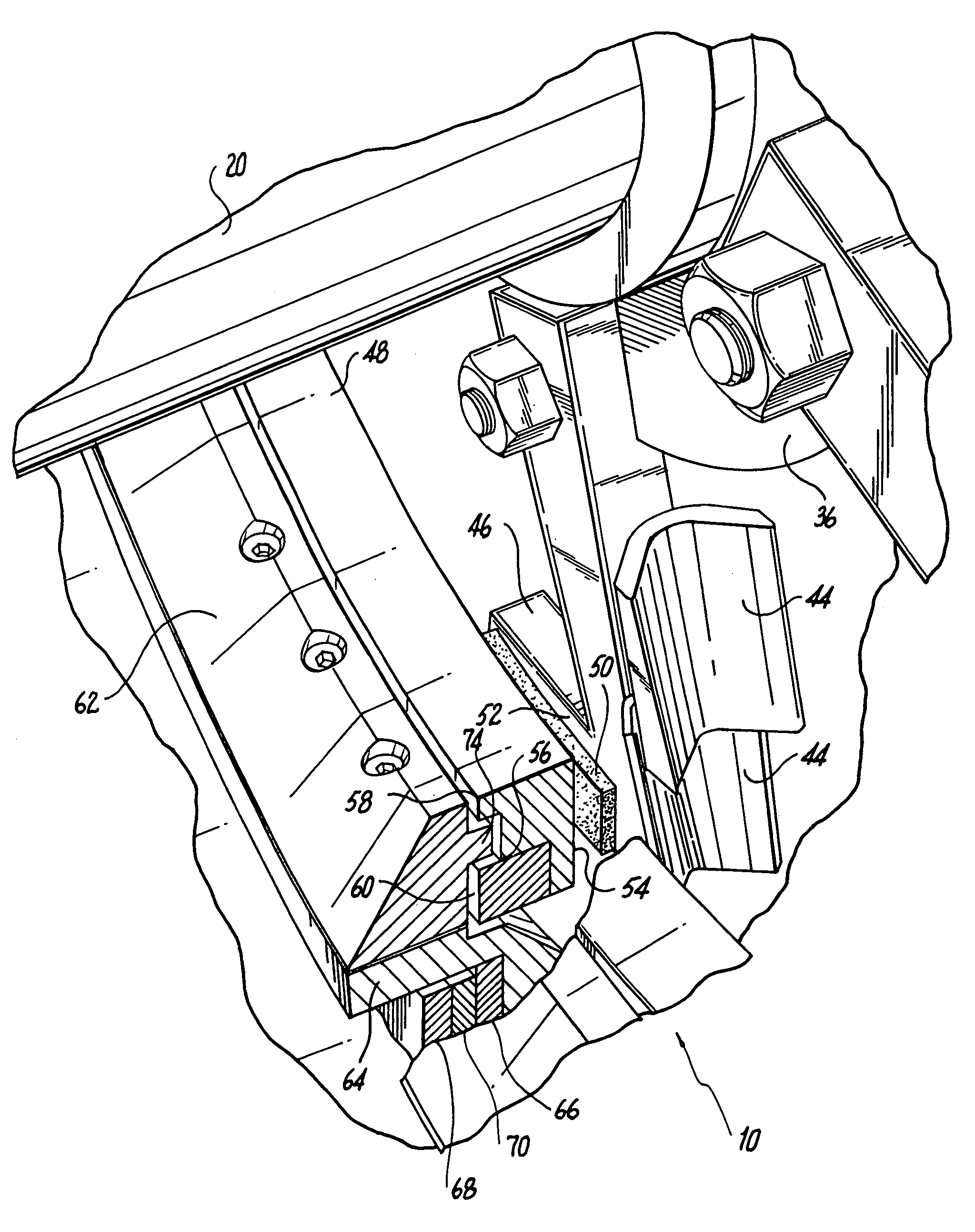
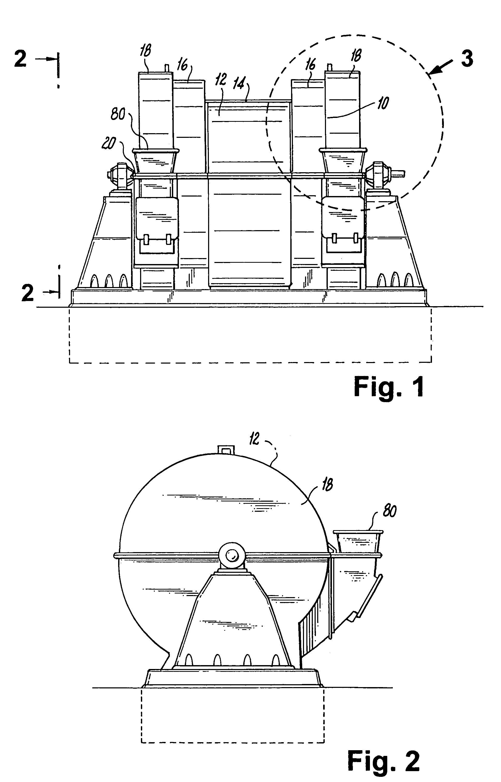
[0026]FIGS. 1 and 2 illustrate the general location of a presently preferred embodiment of a classifier assembly 10, constructed in accordance with the present invention and employed in an exemplary rotary coal pulverizer 12, from t...


PUM


Abstract

The present invention is directed to, among other things, a classifier assembly for mounting on the center shaft of a rotary coal pulverizer which includes a labyrinthian sealing arrangement operatively associated with the shaft for limiting the egress of unacceptably large coal particles from the pulverizer.

Description

BACKGROUND OF THE INVENTION[0001]1. Field of the Invention[0002]The present invention relates to a system and assembly for limiting the egress of particles from a material size reduction process based on the particle size, and more particularly, it concerns an improved classifier assembly for a rotary coal pulverizer.[0003]2. Background of the Related Art[0004]In operations that use coal for fuel, finely-ground coal particles or “fines” are required for efficient operation. The pulverized firing of lower-cost lower-grade coal, coke, or lignite yields higher combustion efficiency than stoker firing, as well as rapid response to load changes. Thus, it is common practice to supply raw coal to a device that will reduce the size of the coal to particles within a desirable range, such as a pulverizer, prior to being used for combustion.[0005]Many pulverizers employ systems and methods including one or more crushing and grinding stages for breaking up the raw coal. It is important to maint...

Claims


Application Information

Patent Timeline
Patent Type & Authority Patents(United States)
IPC IPC(8): B02C23/10B02C13/04B02C13/10B02C13/26B02C23/08
CPCB02C13/04B02C23/08B02C13/26B02C13/10
Inventor LIN, QINGSHENGPENTERSON, CRAIG A.SMITH, DANIEL P.DU VERGER, RICHARD N.
Owner RILEY STOKER
Why Eureka
Try Eureka