Curtain rods and supports therefor

a technology of traverse rods and supports, which is applied in the direction of curtain suspension devices, stands/trestles, kitchen equipment, etc., can solve the problems of prior art traverse rod hangers being subject to jamming and the relative elevation of the rods they support cannot be altered

Inactive Publication Date: 2006-04-18
SOURCE GLOBAL ENTERPRISES
View PDF7 Cites 14 Cited by
  • Summary
  • Abstract
  • Description
  • Claims
  • Application Information

AI Technical Summary

Benefits of technology

[0007]The present invention overcomes the aforestated problems of the prior art by providing a traverse rod having a decorative visible front surface and hangers with decorative elements movable along the front of the rod and other decorative elements stationary on the side brackets of the rod for hanging a front traversing set of curtains with ends, in wrapped around disposition, fixed to the end brackets of the rods. The brackets which support the main set of curtains are adapted to receive secondary brackets which support one or more supplemental sets of curtains mounted rearwardly of the main set of curtains. The main brackets and supplemental brackets can be mounted at varying relative heights in order to compensate for dimensional differences among the various sets of curtains, and to allow replacement curtains, whose dimensions vary from those of the original curtains for which they are substituted, to be hung at the proper height.

Problems solved by technology

Once the prior art brackets are attached to a mounting surface, the relative elevations of the rods they support cannot be altered, as may be required when replacement curtains have dimensions which vary from the original curtains, without making new holes in the mounting surface for changing the position of the brackets.
The hangers on prior art traverse rods are subject to jamming when the wheels on which they ride overlap and become wedged in the track of the rod.

Method used


Image

  • Curtain rods and supports therefor
  • Curtain rods and supports therefor
  • Curtain rods and supports therefor

Examples


Embodiment Construction

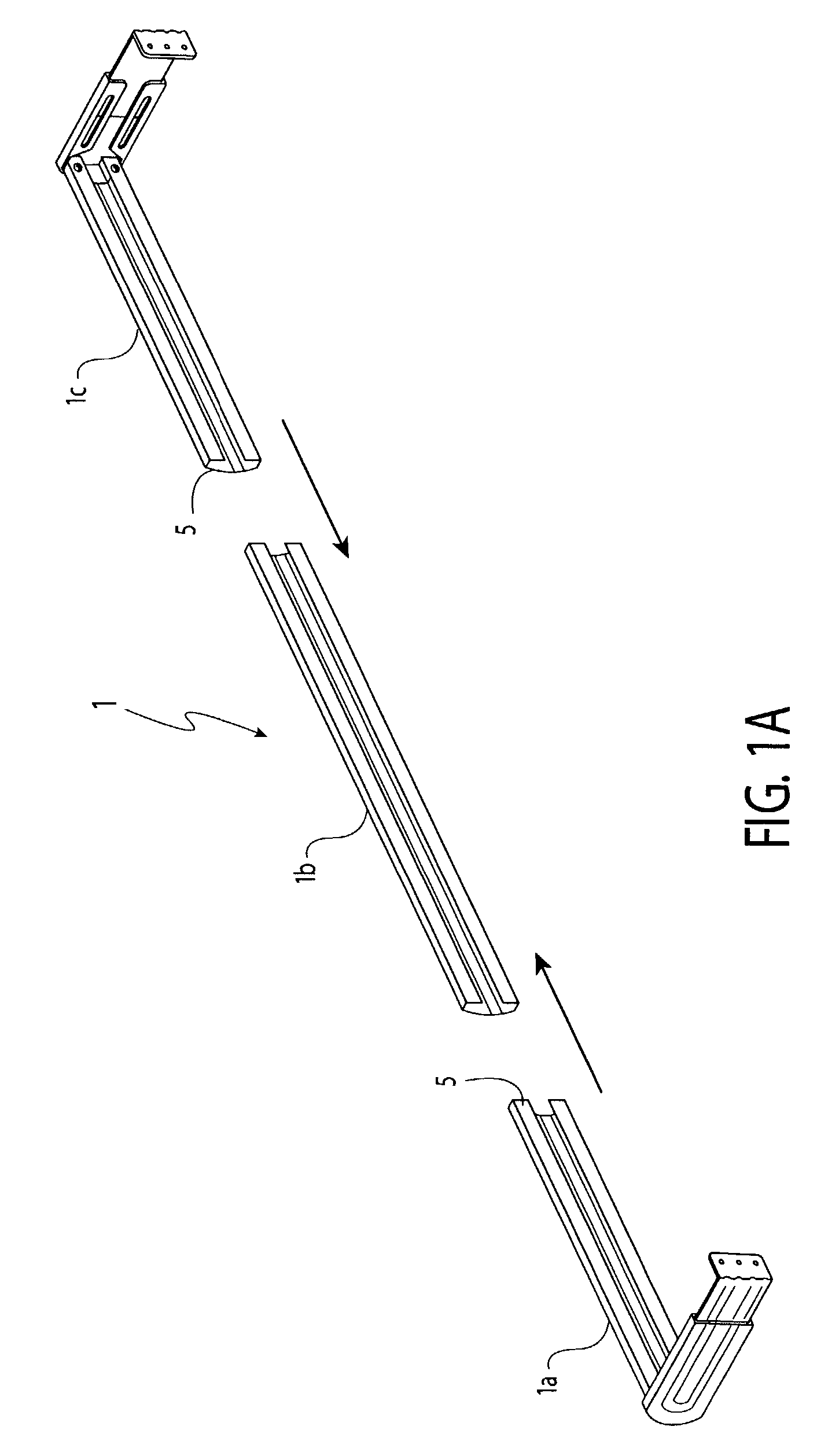
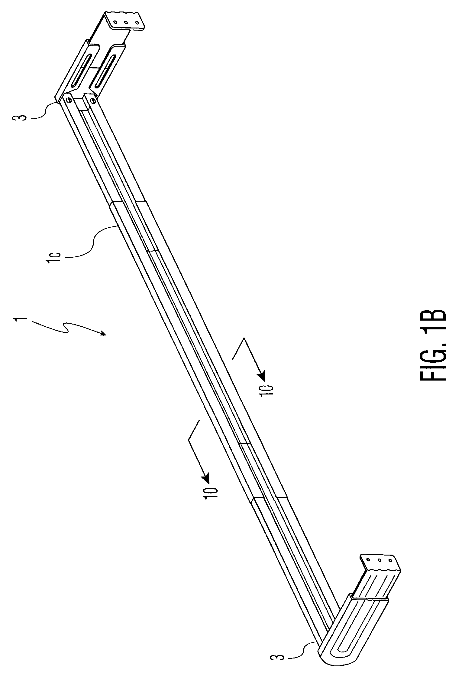
[0028]Referring now to FIGS. 1A and 1B, there is shown a main curtain rod 1, having three telescoping elongated segments 1a, 1b, and 1c. Each of two outermost segments, 1a and 1c, has a free end 3 and an end 5 inserted within the third central segment 1b. As seen in FIG. 2, each segment is preferably formed from sheet metal and bent into a generally C-shaped configuration with parallel top and bottom edges 6 and 8, respectively, running the length of each main rod segment, a convex face 7 extending between the edges 6, 8, which can be viewed when the main rod is hung, and top and bottom spaced lips 9, 11 extending toward one another from the edges 6,8, behind the face 7. An upper channel 13 is formed opposite upper edge 6, between the upper lip 9 and the face 7 of each segment, and a lower channel 15 is formed opposite lower edge 8, between the lower lip 11 and the face 7 of each segment. The cross sectional profile of the central segment 1b is geometrically similar to, and slightly...


PUM


Abstract

A curtain rod has a C-shaped cross section for receiving tongues on main wall mountable main brackets. Slotted supplementary brackets are mountable over the main brackets for permitting one or more supplementary curtain rods to be hung without drilling holes in the wall additional to those provided for the main brackets. Intermediate main and supplemental brackets support long curtain rods between their ends to prevent sagging. The supplemental curtain rod brackets are adapted for hanging the supplemental curtain rods at heights varying from that of the main curtain and the main and supplemental curtain rod brackets are further adapted for independently varying the distance of each set of curtains from the wall. Decorative hangers have rollers for movements along the main curtain rod have bumpers to prevent overlapping of the wheels and resultant binding.

Description

BACKGROUND OF THE INVENTION[0001]The present invention is directed to a novel curtain rod structure which is both aesthetically decorative, able to support multiple sets of curtains, and resistant to binding when operated to traverse the curtains. More specifically, the present invention provides for a main curtain rod which is visible when curtains are suspended from hangers movably mounted on the rod, and one or more supplemental curtain rods, each of which can support a set of curtains. Only one set of brackets need be affixed to the wall or ceiling no matter how many sets of curtains are to be hung. The present invention provides for changing the height of each set of curtains relative to the others to compensate for dimensional differences among the curtains to be hung on the respective rods.[0002]It is known in the art to hang curtains from a wall or ceiling by suspending the curtains on a rod which is connected to a respective bracket at each of its ends, the brackets being a...

Claims


Application Information

Patent Timeline
Patent Type & Authority Patents(United States)
IPC IPC(8): A47H1/10A47H1/08A47H1/124A47H2/00A47H13/01A47H13/04A47H15/02
CPCA47H1/08A47H1/124A47H2/00A47H13/04A47H15/02A47H13/01A47H2001/042
Inventor GOLDSTEIN, ALLAN
Owner SOURCE GLOBAL ENTERPRISES
Why Eureka
Try Eureka