Leadframe package with stable extended leads

a technology of leadframe and lead frame, applied in the field of leadframe packages, can solve the problems of reducing or eliminating the potential for shorting electrical connections in the final package, and achieve the effect of reducing or eliminating the potential for shorting electrical connections, reducing or eliminating downward, side to side deflection, and reducing or eliminating the potential

Active Publication Date: 2017-01-05
STMICROELECTRONICS INT NV
View PDF6 Cites 2 Cited by
  • Summary
  • Abstract
  • Description
  • Claims
  • Application Information

AI Technical Summary

Benefits of technology

[0008]Embodiments of the present disclosure are directed to leadframes having cantilevered leads with that include an integral support on the end of the lead nearest a die pad. A support integral to the leadframe allows the support to be built to the correct height to support the cantilevered lead in each package and reduces or eliminates the upward, downward, and side to side deflections caused or allowed by supports built-in to the tooling of the manufacturing equipment. Also, by building the support into the leadframe, the leadframes may be pretaped prior to the die attach and wire bonding steps of the manufacturing process.
[0009]After the wire bonding and encapsulation steps in a leadframe package manufacturing process, the support structure may be etched away to create a cavity beneath the cantilevered end of the lead. This cavity may remain open or, in some embodiments, the cavity may be refilled or sealed. By etching away or otherwise removing the support, the lead is supported during manufacture of the package, but excess conductive material, which may cause shorting and other problems in the final device, is removed, thereby reducing or eliminating the potential for shorting electrical connections in the final package.

Problems solved by technology

By etching away or otherwise removing the support, the lead is supported during manufacture of the package, but excess conductive material, which may cause shorting and other problems in the final device, is removed, thereby reducing or eliminating the potential for shorting electrical connections in the final package.

Method used


Image

  • Leadframe package with stable extended leads
  • Leadframe package with stable extended leads
  • Leadframe package with stable extended leads

Examples


Embodiment Construction

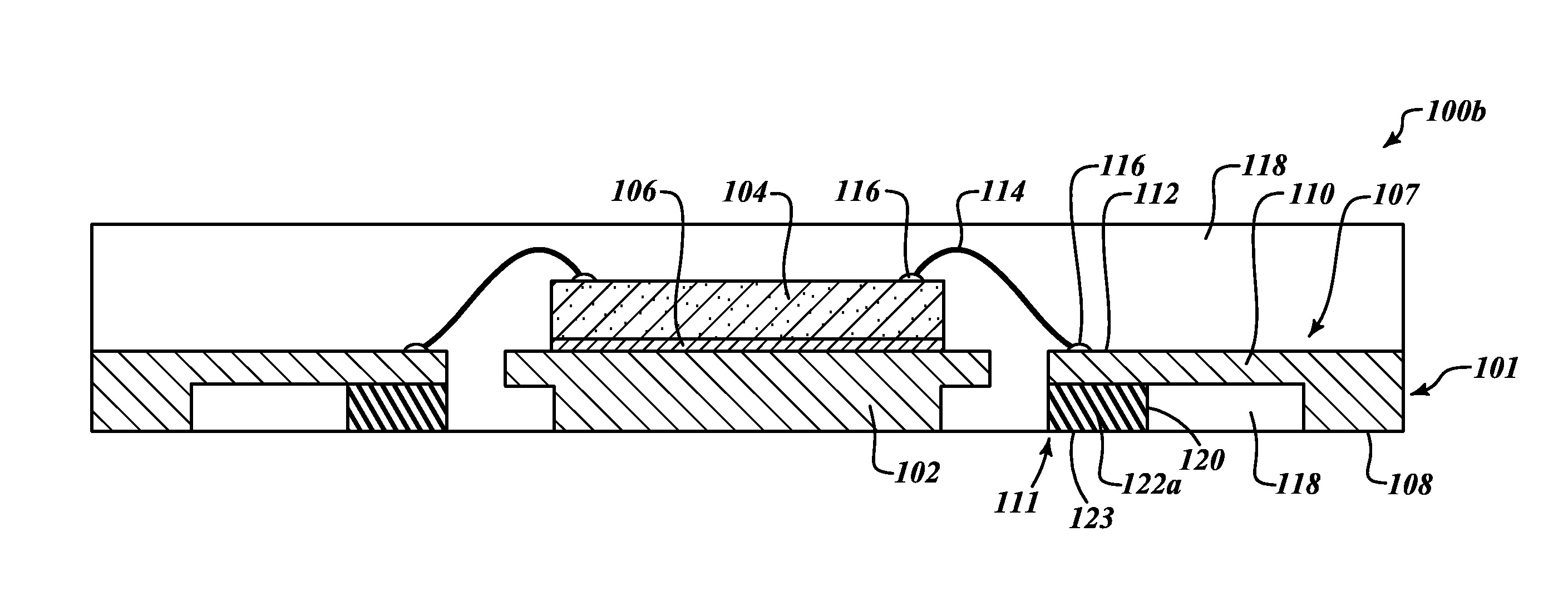
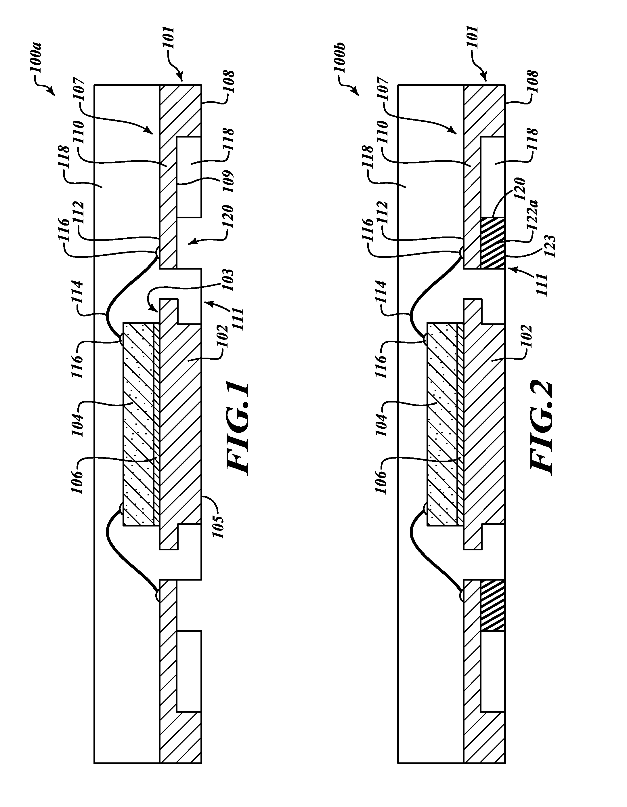
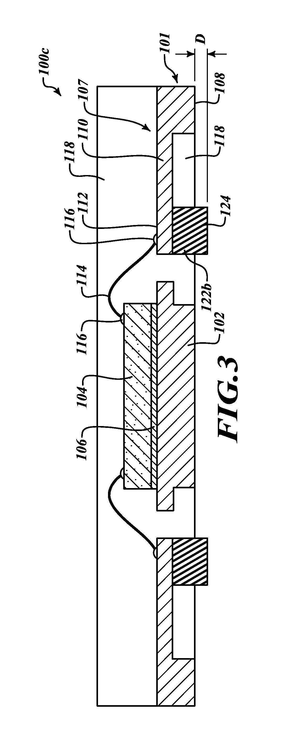
[0017]FIG. 1 shows a cross-sectional view of a leadframe package 100a made in accordance with one embodiment of the disclosure. The leadframe package 100a shows a die pad 102 and two leads 107 located on opposing sides of the die pad 102. The die pad 102 has an upper surface 103 and an opposite lower surface 105 and the leads 107 have upper surface 112 and a lower surface 108. The lower surfaces 108 of the leads 107 may also be referred to as the lands of the package 100a. The die pad 102 and the leads 107 are made of a conductive material, such as copper or a copper alloy.

[0018]The package includes a plurality of leads 107 on each side of the die pad 102. It is to be appreciated that any number of leads may be included in the package including one lead on just one side of the die pad 102. In some embodiments, the leads are provided on two sides or four sides of the die pad. For example, the leads may be on two parallel sides of the package or on four sides of a square or rectangula...


PUM


Abstract

Embodiments of the present disclosure are directed to leadframes having the cantilevered extension that includes an integral support on the end of the lead nearest the die pad. A support integral to the leadframe allows the support to be built to the proper height to support the cantilevered lead in each package and reduces or eliminates the upward, downward, and side to side deflections caused or allowed by supports built-in to the tooling of the manufacturing equipment. Also, by building the support into the leadframe, the leadframes may be pretaped prior to the die attach and wire bonding steps of the manufacturing process.

Description

BACKGROUND[0001]Technical Field[0002]Embodiments of the present disclosure are directed to leadframe packages and methods of manufacturing and assembling leadless packages.[0003]Description of the Related Art[0004]Leadless, or no lead packages are often utilized in applications in which small sized packages are desired. In general, flat leadless packages provide a chip scale or near chip-scale encapsulated package that includes a planar leadframe. Lands located on a bottom surface of the package provide electrical connection to a substrate, such as a printed circuit board (PCB). The leadless packages can be mounted directly on the surface of the PCB using surface mount technology (SMT).[0005]The die in leadframe packages, and in particular quad-flat no lead packages are wire bonded to the ends of the leads in the package. The wire bonding process includes using a force and heat to apply the solder and attach a conductive wire to the lead and a semiconductor die. The leads in the qua...

Claims


Application Information

Patent Timeline
Patent Type & Authority Applications(United States)
IPC IPC(8): H01L23/495H01L23/00H01L23/29H01L23/31H01L21/56
CPCH01L23/31H01L23/495H01L2224/83005H01L23/3121H01L21/568H01L2224/32245H01L2224/48091H01L2224/73265H01L2224/85005H01L2224/48465H01L2924/181H01L2924/00014H01L23/49548H01L21/4828H01L24/32H01L24/73H01L24/85H01L2924/1815H01L23/296H01L24/48H01L23/293H01L2224/48247H01L2924/18301H01L2924/00012H01L2224/45099H01L2224/05599H01L2924/00H01L2224/85399H01L23/49541H01L23/49503H01L24/17H01L23/49531H01L2224/16245H01L2224/81801H01L2224/85801
Inventor TALLEDO, JEFFERSON
Owner STMICROELECTRONICS INT NV
Why Eureka
Try Eureka