Method of detecting a polishing surface of a polishing pad using a polishing head, and polishing apparatus

Inactive Publication Date: 2019-11-21
EBARA CORP
View PDF7 Cites 0 Cited by
  • Summary
  • Abstract
  • Description
  • Claims
  • Application Information

AI Technical Summary

Benefits of technology

[0019]The amount of deflection of the head arm depends on the thrust applied from the polishing head to the polishing pad and does not depend on other factors. Therefore, as long as the thrust is the same, the magnitude of the deflection of the head arm is also the same regardless of the passage

Problems solved by technology

As dressing (or conditioning) of the polishing surface of the polishing pad and polishing of a substrate are repeatedly performed, the polishing pad gradually wears.
When these sliding elements are in motion,

Method used


Image

  • Method of detecting a polishing surface of a polishing pad using a polishing head, and polishing apparatus
  • Method of detecting a polishing surface of a polishing pad using a polishing head, and polishing apparatus
  • Method of detecting a polishing surface of a polishing pad using a polishing head, and polishing apparatus

Examples


Embodiment Construction

[0027]Embodiments will be described below with reference to the drawings.

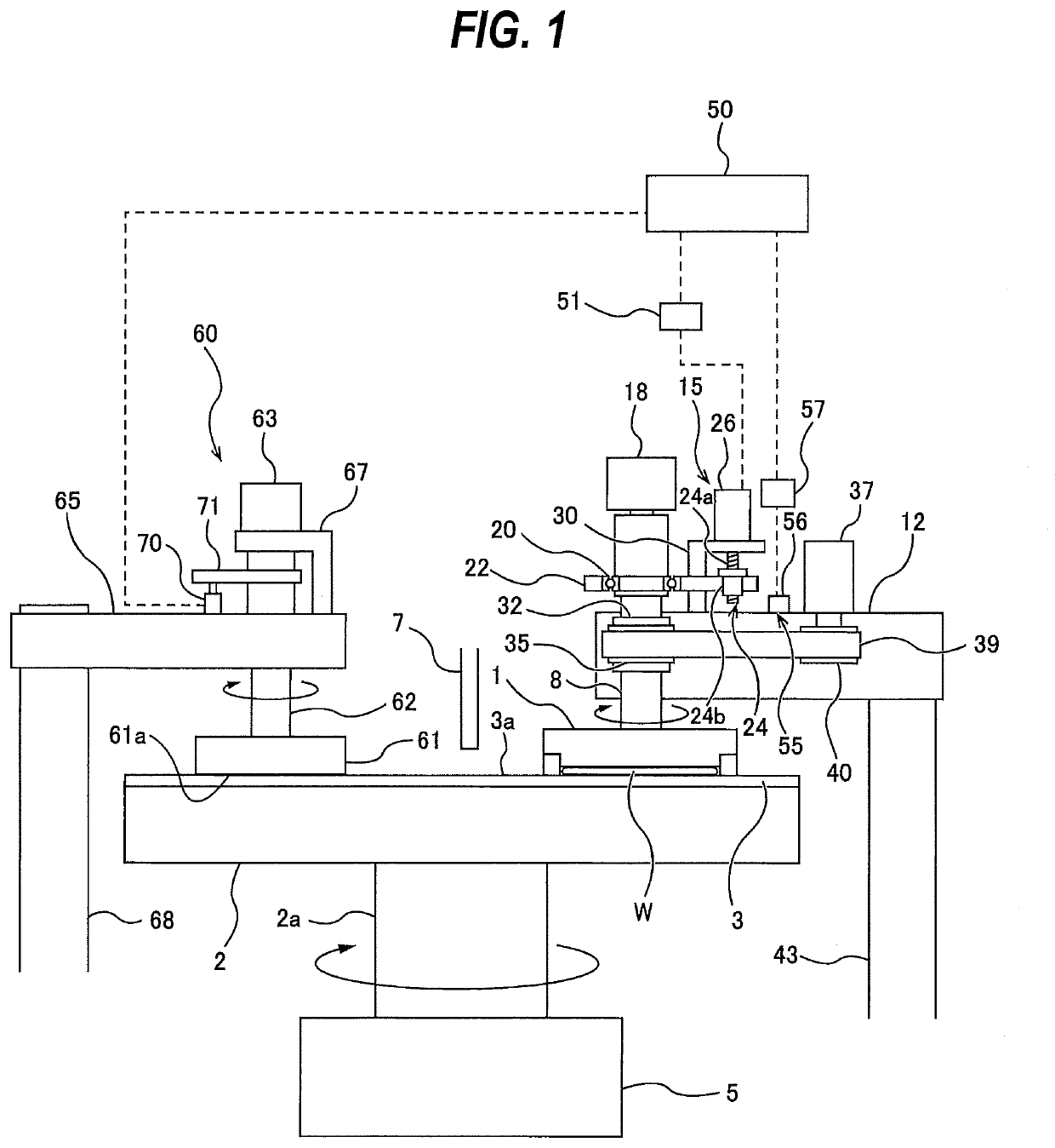
[0028]FIG. 1 is a view showing an embodiment of a polishing apparatus. As shown in FIG. 1, the polishing apparatus includes a polishing table 2 for supporting a polishing pad 3, and a polishing head (or a substrate holder) 1 for holding a wafer W, which is an example of a substrate, and pressing the wafer W against the polishing pad 3 on the polishing table 2.

[0029]The polishing table 2 is coupled through a table shaft 2a to a table motor 5 which is disposed below the polishing table 2, so that the polishing table 2 is rotatable about the table shaft 2a. The polishing pad 3 is attached to an upper surface of the polishing table 2. An upper surface of the polishing pad 3 serves as a polishing surface 3a for polishing the wafer W. A polishing-liquid supply nozzle 7 is provided above the polishing table 2 to supply a polishing liquid (e.g., a slurry) onto the polishing surface 3a of the polishing pad 3.

[0030]The p...


PUM


Abstract

A method capable of accurately detecting a polishing surface of a polishing pad using a polishing head without being influenced by passage of time is disclosed. The includes: moving a polishing head in a direction perpendicular to a polishing surface of a polishing pad while applying thrust from the polishing head to the polishing pad; during the movement of the polishing head, detecting deflection of a head arm with a strain sensor, the head arm supporting the polishing head; and determining a position of the polishing head corresponding to a point in time at which an output signal from the strain sensor reaches a preset threshold value.

Description

CROSS REFERENCE TO RELATED APPLICATION[0001]This document claims priority to Japanese Patent Application Number 2018-096000 filed May 18, 2018, the entire contents of which are hereby incorporated by reference.BACKGROUND[0002]In a manufacturing process of a semiconductor device, it increasingly becomes important to planarize a surface of the semiconductor device. One of the most important planarizing technologies is chemical mechanical polishing (CMP). The chemical mechanical polishing is performed using a polishing apparatus. Specifically, a polishing head presses a substrate, such as a wafer, against a polishing surface of a polishing pad to polish the substrate, while a polishing liquid containing abrasive particles, such as silica (SiO2) or the like, is supplied onto the polishing surface.[0003]As dressing (or conditioning) of the polishing surface of the polishing pad and polishing of a substrate are repeatedly performed, the polishing pad gradually wears. A distance between th...

Claims


Application Information

Patent Timeline
IPC IPC(8): B24B49/16B24B37/27B24B37/005
CPCB24B37/005B24B49/16B24B37/27G01B21/32B24B37/20B24B37/34B24B53/017B24B49/10G01B7/22B24B37/10B24B37/30H01L21/304H01L22/26H01L21/67259H01L21/67092
Inventor UMEMOTO, MASAOKOSUGE, RYUICHIKAMATA, SHUICHIYOSHIDA, KENTO
Owner EBARA CORP
Why Eureka
Try Eureka