Shock absorbing structure of turning mechanism of an electric cart equipped with twin front wheels

a technology of electric carts and turning mechanisms, which is applied in the direction of steering links, wheelchairs/patient conveyances, transportation and packaging, etc., can solve the problems of prone to fall, increased manufacturing cost and weight of carts, and unsatisfactory four-wheel electric carts

Inactive Publication Date: 2006-04-18
SUNPEX TECH
View PDF2 Cites 8 Cited by
  • Summary
  • Abstract
  • Description
  • Claims
  • Application Information

AI Technical Summary

Benefits of technology

[0007]The present turning mechanism is equipped with twin front wheels, a control shaft, and an axle. The shaft has a horizontal rod portion at a lower end. The front wheels are connected to two ends of the axle while the axle is arranged under the horizontal rod portion. The front wheels are much closer to each other than both rear wheels are to each other. Elastic elements are located between the axle and the horizontal rod portion while connecting plates are arranged next to front and rear sides of the horizontal rod portion and the axle. Each connecting plate has two fitting holes respectively opposing a through hole of the horizontal rod portion, and a through hole of the axle. Ringed pads are inserted in respective fitting holes, and bolts are inserted through the ringed pads, and the through holes. Thus, the present electric cart is like a four-wheel one in terms of stability, and is like a three-wheel one in terms of easiness to use and simplicity of the structure.

Problems solved by technology

This three-wheel cart has a disadvantage that it is prone to fall over when it tilts too much in turning.
Consequently, a turning mechanism of one such four-wheel electric cart will have a more complicated structure, and the manufacturing cost and weight of the cart will increase.
Therefore, such four-wheel electric carts are not ideal.
Moreover, some countries impose relatively strict regulations on the manufacturing and sale of such four-wheel electric carts.

Method used


Image

  • Shock absorbing structure of turning mechanism of an electric cart equipped with twin front wheels
  • Shock absorbing structure of turning mechanism of an electric cart equipped with twin front wheels
  • Shock absorbing structure of turning mechanism of an electric cart equipped with twin front wheels

Examples


Embodiment Construction

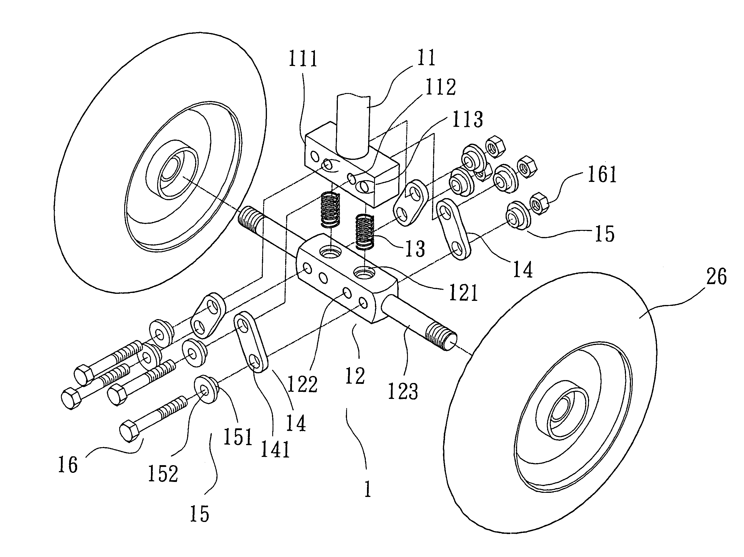
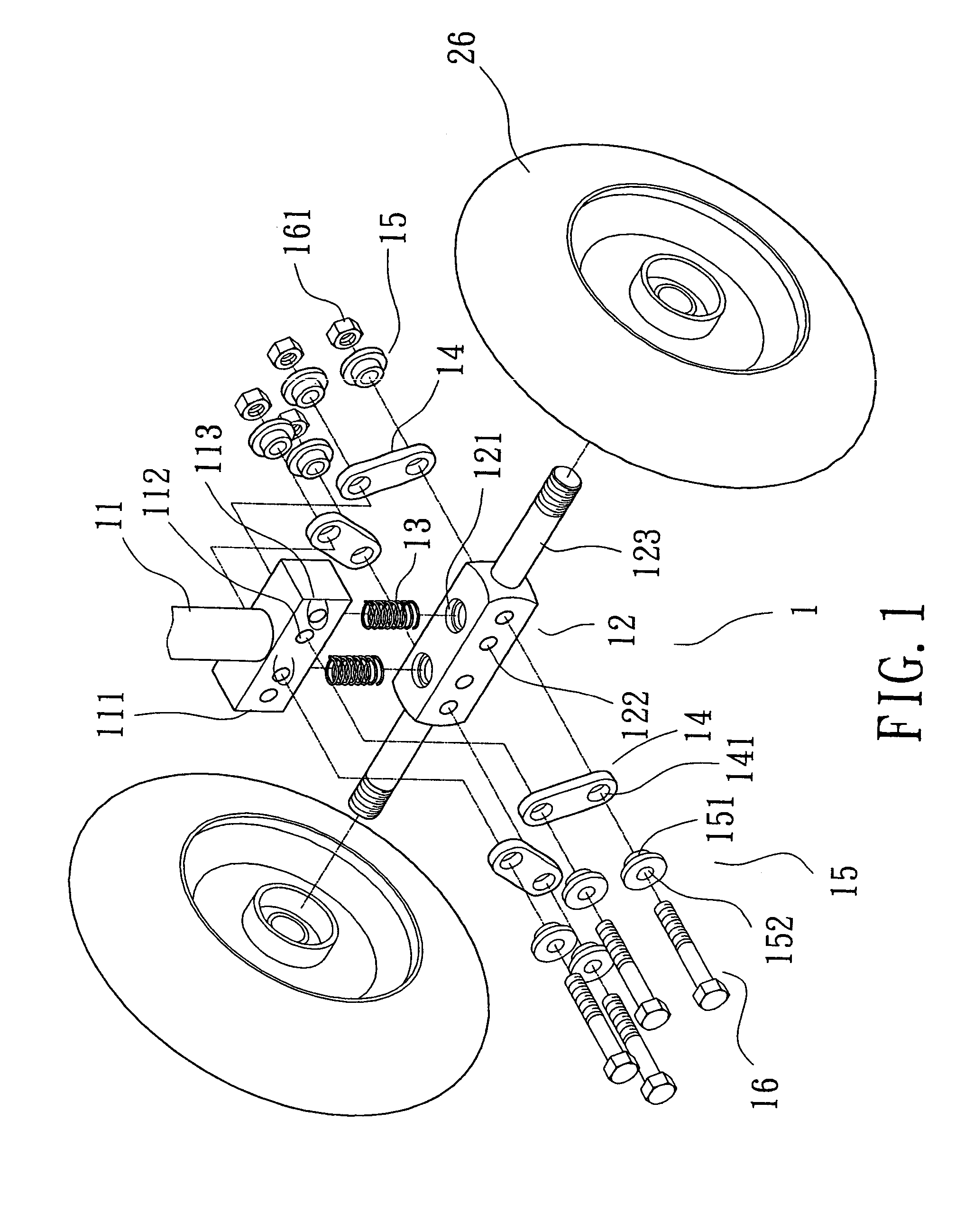
[0018]Referring to FIG. 1, a preferred embodiment of an electric cart in the present invention is equipped with a turning mechanism 1, which includes a control shaft 11, an axle 12, elastic elements 13, connecting plates 14, ringed pads 15, bolts 16, and two front wheels 26.

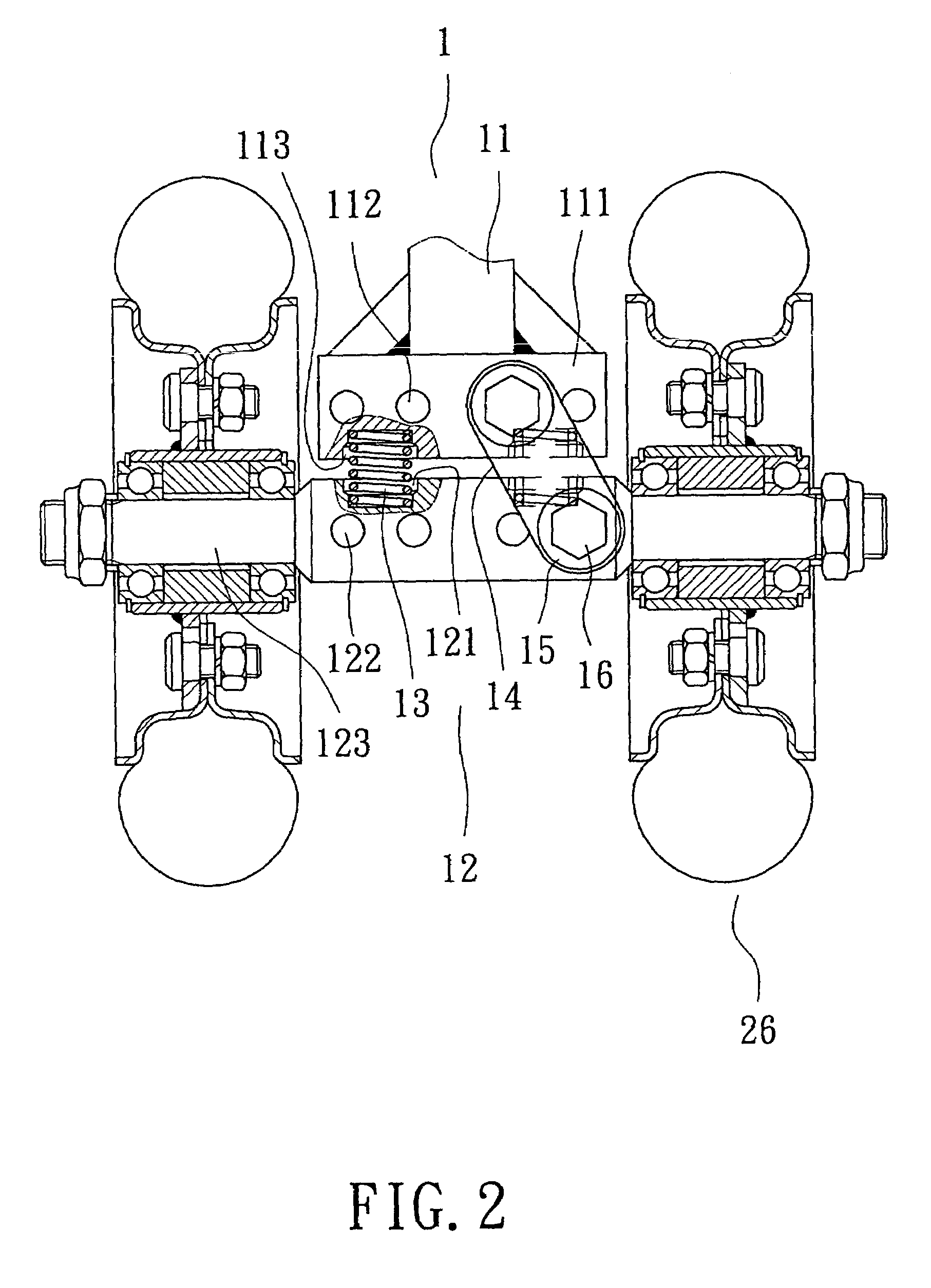
[0019]Referring to FIGS. 1 to 3, the control shaft 11 is inserted in a holding tube 25 projecting upwards from a front end of a frame 21 of the electric cart, and is connected with the front wheels 26 at a lower end, and handlebars 23 at an upper end. The control shaft 11 has a horizontal rod portion 111 at the lower end, which is formed with several through holes 112 extending from a front side to a rear side thereof, and hollows 113 on a lower side.

[0020]The axle 12 is formed with several through holes 122 extending from a front side to a rear side of a middle portion thereof, and hollows 121 on an upper side.

[0021]Each of the connecting plates 14 has fitting holes 141 at two ends. The ringed pads 15 are made o...


PUM


Abstract

A turning mechanism of an electric cart includes twin front wheels, a control shaft, and an axle; the shaft has a horizontal rod portion at a lower end; the front wheels are connected to two ends of the axle while the axle is arranged under the horizontal rod portion; the front wheels are much closer to each other than rear wheels are to each other; springs are located between the axle and the horizontal rod portion; connecting plates are arranged next to fronts and rears of the horizontal rod portion and the axle, and each has two fitting holes respectively opposing a through hole of the horizontal rod portion, and a through hole of the axle; ringed pads are inserted in respective fitting holes, and bolts are inserted through the ringed pads, and the through holes; thus, the cart is like a three-wheel one in terms of easiness to use and simplicity of the structure.

Description

BACKGROUND OF THE INVENTION[0001]1. Field of the Invention[0002]The present invention relates to a turning mechanism of an electric cart equipped with twin front wheels, more particularly one, which are provided with an axle, a control shaft, and elastic elements disposed between the axle and a lower horizontal rod portion of the control shaft such that shock of the electric cart can be absorbed when the electric cart is used.[0003]2. Brief Description of the Prior Art[0004]Referring to FIG. 9, a conventional electric cart 2 includes a frame 21, a chair 22 disposed on a rear end of the frame 21, a holding tube 25 projecting from a front end of the frame 21, a control shaft (not numbered) inserted through and supported by the holding tube 25, handlebars 23 coupled to an upper end of the control shaft, a front wheel 26 connected to a lower end of the control shaft, and two rear wheels 24 arranged at rear corners of the frame 21. This three-wheel cart has a disadvantage that it is pron...

Claims


Application Information

Patent Timeline
Patent Type & Authority Patents(United States)
IPC IPC(8): B62D7/06A61G5/04B60G3/00B60G9/02B62D1/16
CPCB60G3/00B60G9/02B60G2300/24B60G2300/122
Inventor LIN, SAMUEL
Owner SUNPEX TECH
Why Eureka
Try Eureka