Plasma display panel having dummy barrier ribs

a technology of barrier ribs and plasma, which is applied in the direction of gas exhaustion means, discharge tubes luminescnet screens, discharge tubes, etc., can solve the problems of gap formation between one of the two substrates and the barrier ribs, and noise generation during pdp operation

Inactive Publication Date: 2006-04-18
SAMSUNG SDI CO LTD
View PDF8 Cites 8 Cited by
  • Summary
  • Abstract
  • Description
  • Claims
  • Application Information

AI Technical Summary

Benefits of technology

[0020]In a further exemplary embodiment according to the present invention is provided a plasma display panel, which includes first and second substrates facing one another and having a gap therebetween. Each substrate is substantially rectangular in shape with long side edges and short side edges and has a discharge region and non-discharge regions that surround the discharge region. The plasma display panel has a plurality of barrier ribs mounted between the substrates on the discharge region and at least one barrier rib mounted between the substrates on at least one of the non-discharge regions that are adjacent to the long side edges of the substrates, so as to provide support to the substrates when a sealing pressure is applied to the substrates.

Problems solved by technology

As a result, when manufacturing the PDP structured in this manner, gaps are formed between one of the two substrates and the barrier ribs during the sealing and exhausting (i.e., vacuuming) processes.
These gaps result in the generation of noise during operation of the PDP.
If these gaps remain in the final PDP product after sealing the substrates and performing other final processes, noise is generated during operation of the PDP as described above.
This significantly reduces the overall quality of the PDP.

Method used


Image

  • Plasma display panel having dummy barrier ribs
  • Plasma display panel having dummy barrier ribs
  • Plasma display panel having dummy barrier ribs

Examples


Embodiment Construction

[0029]Exemplary embodiments of the present invention will now be described in detail with reference to the accompanying drawings.

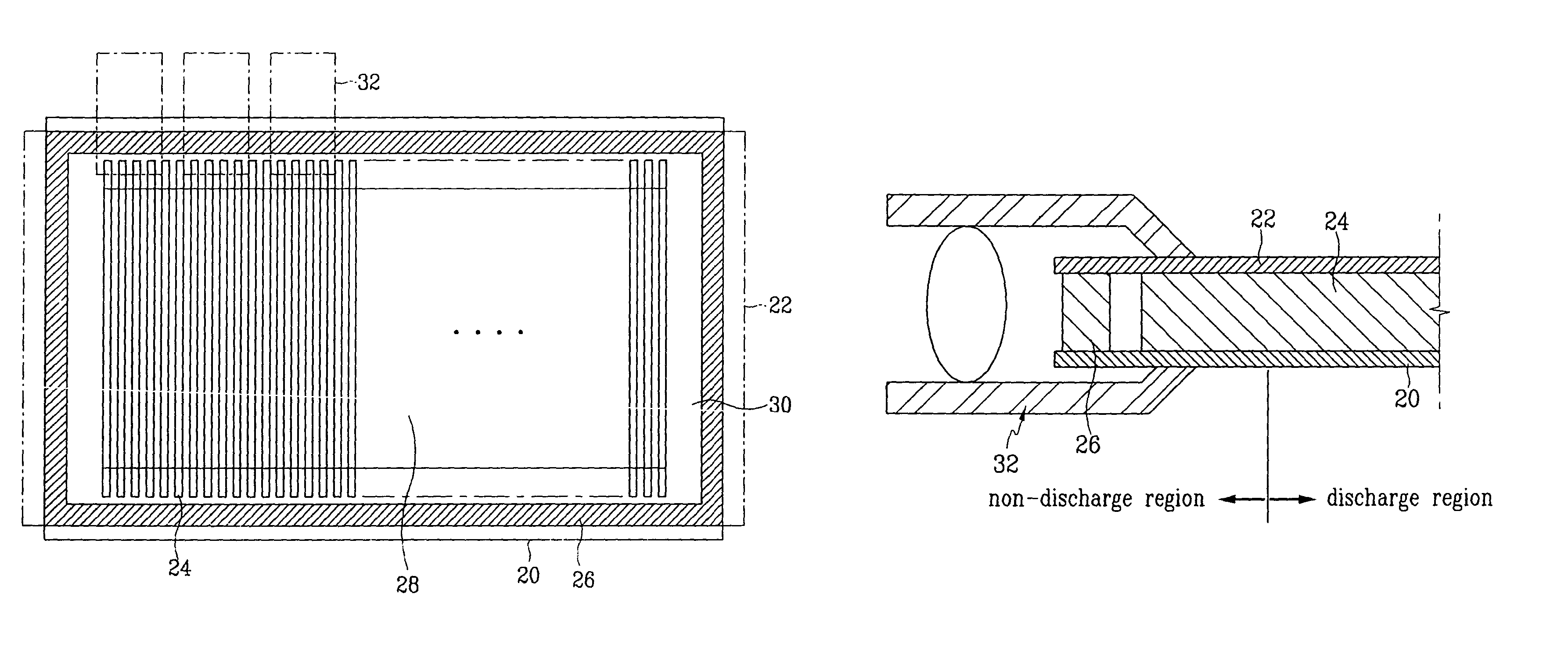
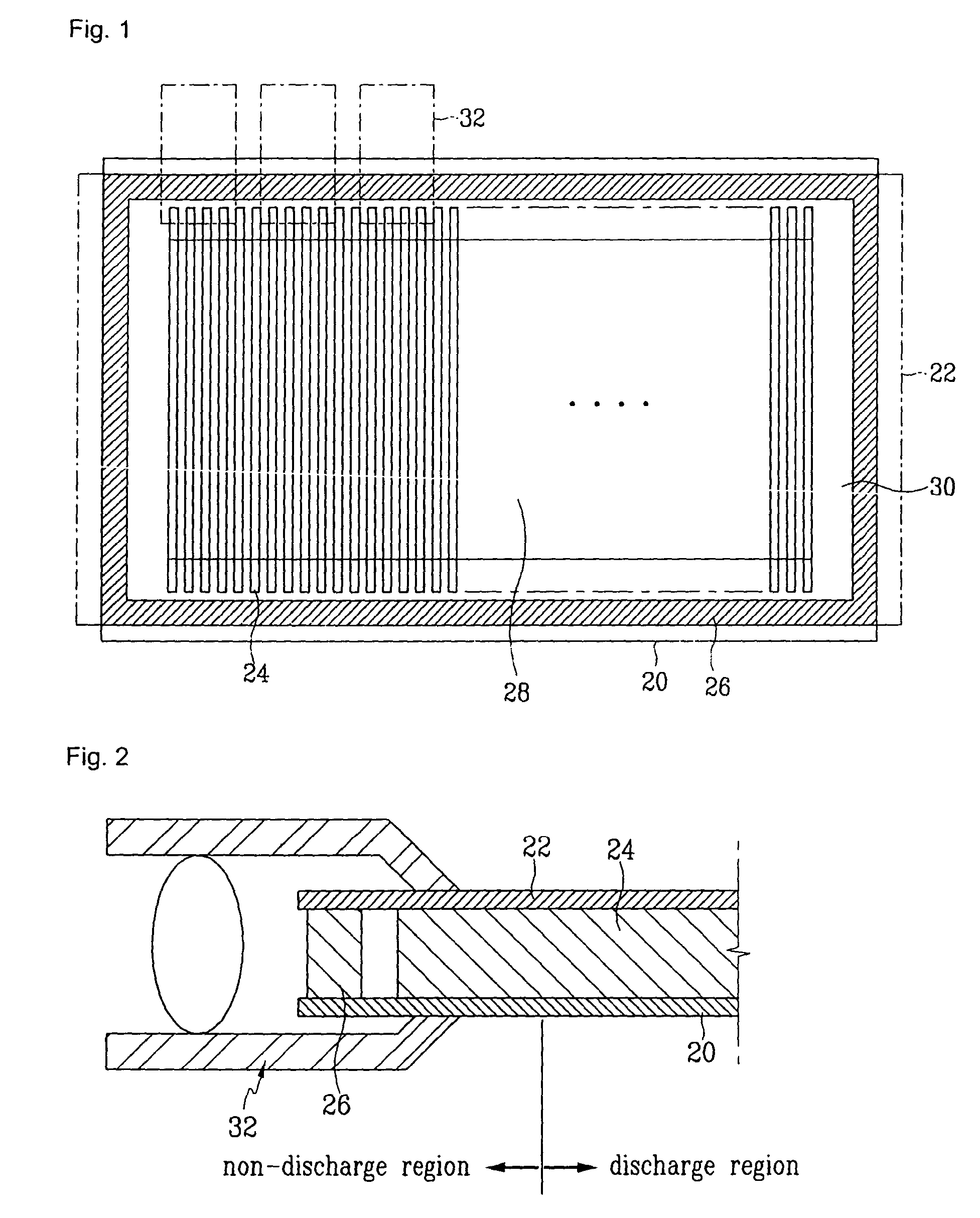
[0030]FIG. 1 is a schematic plan view of a plasma display panel according to an exemplary embodiment of the present invention. As shown in FIG. 1, the plasma display panel (PDP) includes a transparent first substrate (or lower substrate) 20 and a transparent second substrate (or upper substrate) 22. The substrates 20 and 22 are formed in a substantially rectangular shape having long side edges (in a horizontal direction) and short side edges (in a vertical direction). The first substrate 20 and the second substrate 22 oppose (i.e., face) one another and are substantially parallel to one another. The substrates 20 and 22 have a predetermined gap therebetween.

[0031]Barrier ribs 24 that define discharge cells are mounted between the substrates 20 and 22. Also formed between the substrates 20 and 22 is a discharge mechanism (not shown) realized through dischar...


PUM


Abstract

A plasma display panel (PDP) includes a first substrate and a second substrate opposing one another with a predetermined gap therebetween. The first substrate and the second substrate are substantially rectangular in shape with long side edges and short side edges, and are interconnected by frit deposited between the first substrate and the second substrate. The substrates have a predetermined discharge region and predetermined non-discharge regions that surround the discharge region. The PDP also includes barrier ribs mounted between the first substrate and the second substrate. The barrier ribs are mounted at least partly on the discharge region, and at least partly on the non-discharge regions that are adjacent to the long side edges of the substrates.

Description

CROSS-REFERENCE TO RELATED APPLICATIONS[0001]This application claims priority to and the benefit of Korean Patent Application No. 2002-0057578 filed on Sep. 23, 2002 in the Korean Intellectual Property Office, the entire content of which is incorporated herein by reference.BACKGROUND OF THE INVENTION[0002](a) Field of the Invention[0003]The present invention relates to a plasma display panel (PDP), and more particularly, to a PDP that forms dummy barrier ribs in non-display regions.[0004](b) Description of the Related Art[0005]Plasma display panels (PDPs) are emerging as one of the most popular flat panel display configurations used for wall-mounted televisions and other similar large-screen display applications. Predetermined images are displayed on the PDP using a discharge mechanism of discharge cells. The PDPs typically include a centrally located display region (i.e., discharge region) surrounded by non-display regions (i.e., non-discharge regions). For example, for a rectangul...

Claims


Application Information

Patent Timeline
Patent Type & Authority Patents(United States)
IPC IPC(8): H01J17/49H01J11/12H01J11/36H01J11/54
CPCH01J11/12H01J11/54H01J11/36H01J2211/368
Inventor KO, JI-SUNGHEO, EUN-GIKIM, WOO-TAE
Owner SAMSUNG SDI CO LTD
Why Eureka
Try Eureka