Image display system, information processing apparatus, and method of controlling the same

a technology of information processing apparatus and image display system, which is applied in the direction of electrical apparatus, color television details, instruments, etc., can solve the problem that the observer cannot always obtain a proper stereoscopic vision

Inactive Publication Date: 2006-04-18
CANON KK
View PDF17 Cites 52 Cited by
  • Summary
  • Abstract
  • Description
  • Claims
  • Application Information

AI Technical Summary

Benefits of technology

[0019]It is still another object of the present invention to always allow a proper stereoscopic vision without changing the contents displayed in a window.
[0020]It is still another object of the present inventio...

Problems solved by technology

As a result, the optimal observation position changes, and he...

Method used


Image

  • Image display system, information processing apparatus, and method of controlling the same
  • Image display system, information processing apparatus, and method of controlling the same
  • Image display system, information processing apparatus, and method of controlling the same

Examples


first embodiment

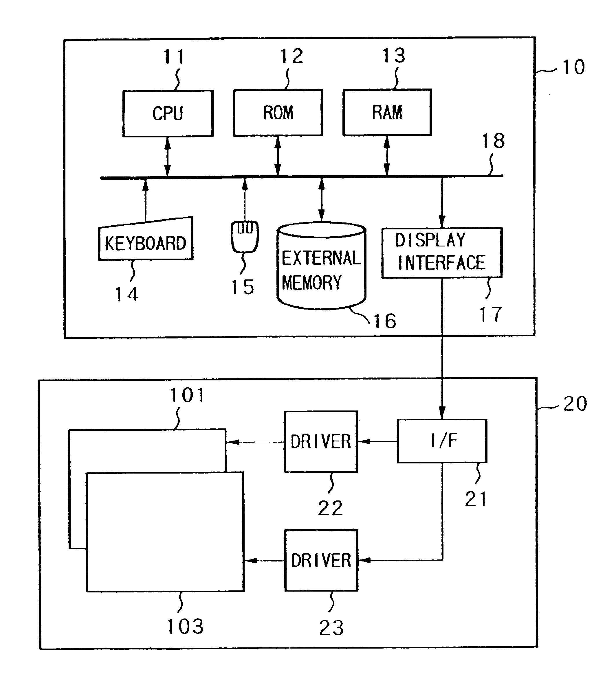
[0052]FIG. 1 is a block diagram showing the arrangement of a computer system according to the Referring to FIG. 1, reference numeral 10 denotes a host computer; 20, a stereoscopic display apparatus; 11, a CPU for realizing various types of control operations performed by the host computer 10; 12, a ROM storing a boot program, which is executed when the CPU 11 is started, and various types of data; and 13, a RAM which serves as a main memory for storing control programs executed by the CPU 11 and provides a work area used when the CPU 11 executes various types of control operations. Reference numerals 14 and 15 respectively denote a keyboard and a pointing device, which are used to input commands from the user. Reference numeral 16 denotes an external memory such as a hard disk, which is used to store various application programs and data. Note that each application program stored in the external memory 16 is loaded into the main memory area of the RAM 13 when it is executed by the ...

second embodiment

[0070]FIG. 11 is a flow chart showing an operation procedure performed by the host computer in the In step S20, the host computer 10 detects that a window for stereoscopic image display is opened or its position is moved. Opening or movement of a window is detected in the above manner. In step S21, the host computer 10 checks the position of the window to detect whether the window is at a position where a proper stereoscopic vision is realized. If the window position is at a proper position, the current state is maintained. If the window position is not at a proper position, the flow advances to step S22 to automatically change the contents of a displayed image.

[0071]Processing of changing the contents of the displayed image in step S22 will be described in detail next. FIGS. 12 to 16 explain how the contents of the displayed image within the window are changed.

[0072]When the displayed image is a vertically striped parallax image, one of the following changing operations is perform...

third embodiment

[0087]FIG. 17 is a flow chart showing a control procedure performed by the host computer in the When the host computer 10 detects in step S30 that a window is opened or moved, the flow advances to step S31. In step S31, if it is determined on the basis of the position of the window after it is opened or moved that the window is a window to be subjected to stereoscopic image display, the host computer 10 checks the position of the window after it is opened or moved, and determines whether the window is at a position where a proper stereoscopic vision is obtained. If it is determined that the window is at the proper position, the host computer 10 continues the current state. Otherwise, the flow advances to step S32 to automatically change the state of the directivity control means.

[0088]The state of this directivity control means is changed as follows.

[0089]When the displayed image is a vertically striped parallax image, the directivity control means is moved to the right or left by ...


PUM


Abstract

A stereoscopic image display apparatus for displaying a stereoscopic image, which is obtained by alternately arranging stripe parallax images R and L corresponding to the right and left eyes, in a window includes a parallax barrier for a stereoscopic vision. When the display position of a window including a stereoscopic image which is set after the window is opened or moved and the positions of the right-eye and left-eye stripes of a parallax barrier have a relationship which does not allow a proper stereoscopic vision, the display position of the window is moved by one stripe in the horizontal direction.

Description

BACKGROUND OF THE INVENTION[0001]1. Field of the Invention[0002]The present invention relates to a stereoscopic display apparatus which allows an observer to observe a stereoscopic image by using the parallax between the right and left eyes, an information processing apparatus, a host computer for controlling the display apparatus, and a method therefor, thereby providing an operation environment for comfortable stereoscopic display.[0003]2. Related Background Art[0004]In general, a stereoscopic image display apparatus of the parallax barrier scheme is known well as an apparatus for displaying a stereoscopic image. The parallax barrier scheme is disclosed in S. H. Kaplan, “Theory of Parallax Barriers.”, J. SMPTE, Vol. 59, No. 7, pp. 11-21 (1952). According to this scheme, a striped image obtained by alternately arranging at least right and left images of a plurality of parallax images from a plurality of viewpoints into a vertically striped pattern is observed through a slit pattern...

Claims


Application Information

Patent Timeline
IPC IPC(8): H04N13/04G02B30/30G09G5/14G09G5/36H04N13/00H04N15/00
CPCG02B27/2214H04N13/0275H04N13/0497H04N13/0409H04N13/0425H04N13/0456H04N13/0486G09G5/14H04N13/0003H04N13/0048H04N13/0055H04N13/0404H04N13/0434H04N13/0285H04N13/337H04N13/305H04N13/275H04N13/189H04N13/31H04N13/161H04N13/315H04N13/10H04N13/286H04N13/361H04N13/327H04N13/398G02B30/30G02B30/27
Inventor SUDO, TOSHIYUKI
Owner CANON KK
Why Eureka
Try Eureka