Louvered rack

a rack and loud technology, applied in the field of loud racks, can solve the problems of over-predetermined temperature range, increased operating expenses of conventional cooling systems, and problems such as problems such as cooling of data centers,

Inactive Publication Date: 2006-04-18
HEWLETT PACKARD DEV CO LP
View PDF7 Cites 166 Cited by
  • Summary
  • Abstract
  • Description
  • Claims
  • Application Information

AI Technical Summary

Benefits of technology

[0006]According to one embodiment, the present invention pertains to a rack having a frame for supporting one or more electronic components. A front panel and a rear panel a

Problems solved by technology

As such, the cooling of data centers presents problems in addition to those faced with the cooling of the racks.
In this respect, conventional cooling systems often attempt to cool components that are not operating at a level which may cause their temperatures to exceed a predetermined temperature range.
Consequently, conventional cooling systems often incur greater amounts of operating expenses than may be necessary to sufficiently cool the heat gen

Method used


Image

  • Louvered rack
  • Louvered rack
  • Louvered rack

Examples


Embodiment Construction

[0019]For simplicity and illustrative purposes, the present invention is described by referring mainly to an exemplary embodiment thereof. In the following description, numerous specific details are set forth in order to provide a thorough understanding of the present invention. It will be apparent however, to one of ordinary skill in the art, that the present invention may be practiced without limitation to these specific details. In other instances, well known methods and structures have not been described in detail so as not to unnecessarily obscure the present invention.

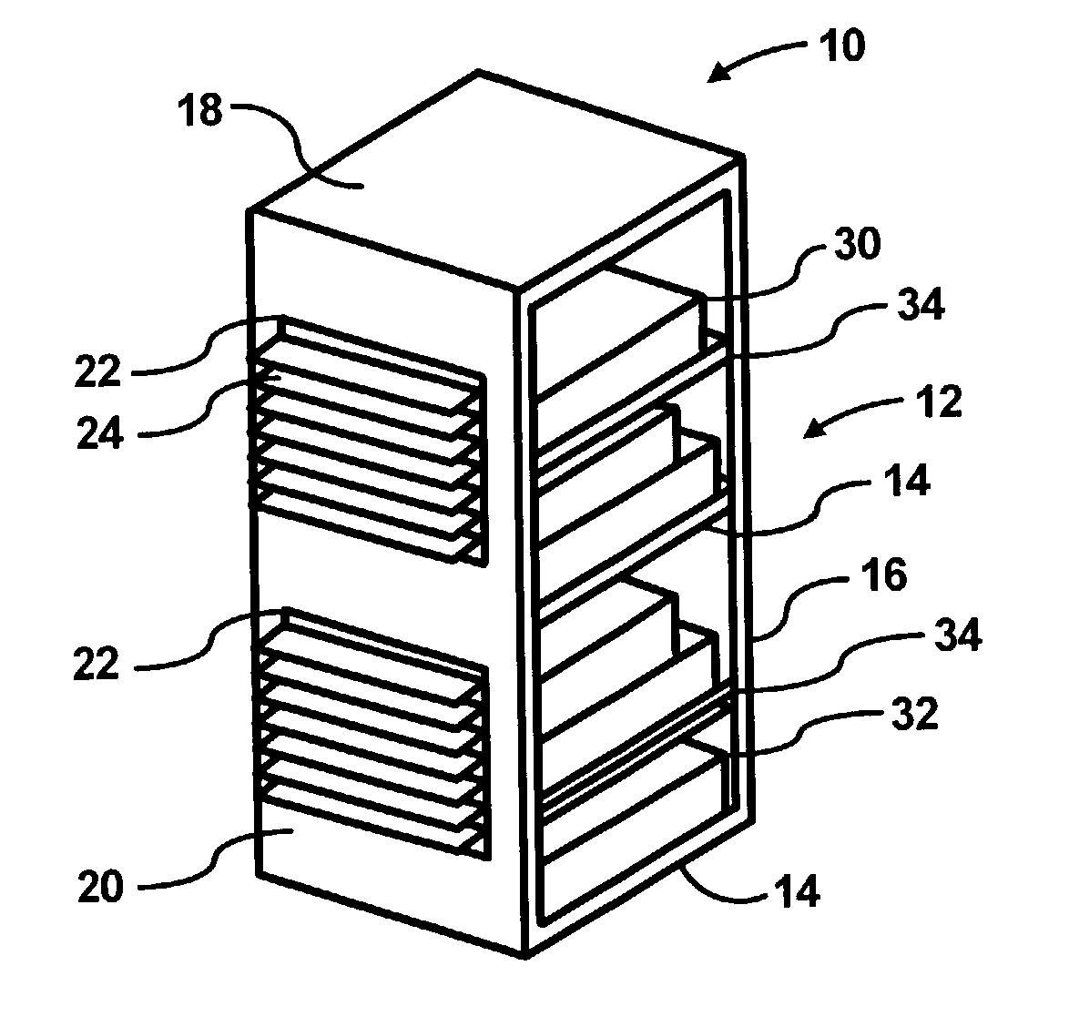
[0020]Throughout the present disclosure, reference is made to “cooling fluid” and “heated air”. For purposes of simplicity, “cooling fluid” may generally be defined as air that has been cooled by a cooling device, e.g., an air conditioning unit. In addition, “heated air” may generally be defined as air, or cooling fluid, that has been heated, e.g., cooling fluid that has received heat from a heat generating compo...


PUM


Abstract

A rack has a frame for supporting one or more electronic components. A front panel and a rear panel are attached to the frame. At least one of the front panel and the rear panel comprises a vent having at least one movable louver configured to vary airflow through the vent.

Description

BACKGROUND OF THE INVENTION[0001]A data center may be defined as a location, e.g., room, that houses computer systems arranged in a number of racks. A standard rack, e.g., electronics cabinet, is defined as an Electronics Industry Association (EIA) enclosure, 78 in. (2 meters) wide, 24 in. (0.61 meter) wide and 30 in. (0.76 meter) deep. These racks are configured to house a number of computer systems, e.g., about forty (40) systems, with future configurations of racks being designed to accommodate up to eighty (80) systems. The computer systems typically include a number of components, e.g., one or more of printed circuit boards (PCBs), mass storage devices, power supplies, processors, micro-controllers, semi-conductor devices, and the like, that may dissipate relatively significant amounts of heat during the operation of the respective components. For example, a typical computer system comprising multiple microprocessors may dissipate approximately 250 W of power. Thus, a rack cont...

Claims


Application Information

Patent Timeline
IPC IPC(8): H05K7/20
CPCH05K7/20736H05K7/20718F24F2221/40
Inventor BASH, CULLEN EDWINSHARMA, RATNESH K.
Owner HEWLETT PACKARD DEV CO LP
Why Eureka
Try Eureka