Image rejection mixer with mismatch compensation

a mixer and mismatch technology, applied in the direction of transmission, frequency-changer modification, oscillation generator, etc., can solve the problems of high cost of band pass filtering and difficulty in meeting these requirements

Inactive Publication Date: 2006-04-18
INTEGRANT TECH
View PDF2 Cites 19 Cited by
  • Summary
  • Abstract
  • Description
  • Claims
  • Application Information

AI Technical Summary

Benefits of technology

[0027]According to other aspect of the present invention, an image rejection mixer is provided, which comprises: first and second mixers, each of which mixes an input signal with each of first local oscillation in-phase signal and first local oscillation quadrature-phase signal, respectively, wherein the first local oscillation quadrature-phase signal is resulted by shifting the first local oscillation in-phase signal by −90°; first and second analogue to digital converting means, each of which transforms each output of the first and second mixers to digital signal; third and fourth mixers, each of which mixes output of the first analogue to digital converting means with each of second local oscillation in-phase signal and second local oscillation quadrature-phase signal, respectively, wherein the second local oscillation quadrature-phase signal is resulted by shifting the second local oscillation in-phase signal by −90°; fifth and sixth mixers, each of which mixes output of the second analogue to digital converting means with each of second local oscillation in-phase signal and second local oscillation quadrature-phase signal, respectively; means for subtracting output of the sixth mixer from output of the third mixer; means for adding outputs of the fourth and fifth mixers; and means for reducing difference between 90° and phase difference between the first local oscillation in-phase and quadrature-phase signals by controlling the output of the means for subtracting and the means for adding.

Problems solved by technology

However, the band pass filtering method costs high, since the cost to make a band pass filter is usually high.
It is also known in the art that it is not easy to meet these requirements merely by making or changing design for a circuit and modifying layout of a circuit.

Method used


Image

  • Image rejection mixer with mismatch compensation
  • Image rejection mixer with mismatch compensation
  • Image rejection mixer with mismatch compensation

Examples


Embodiment Construction

[0041]Hereinafter, preferred embodiments of the present invention will be described in detail with reference to the attached drawings.

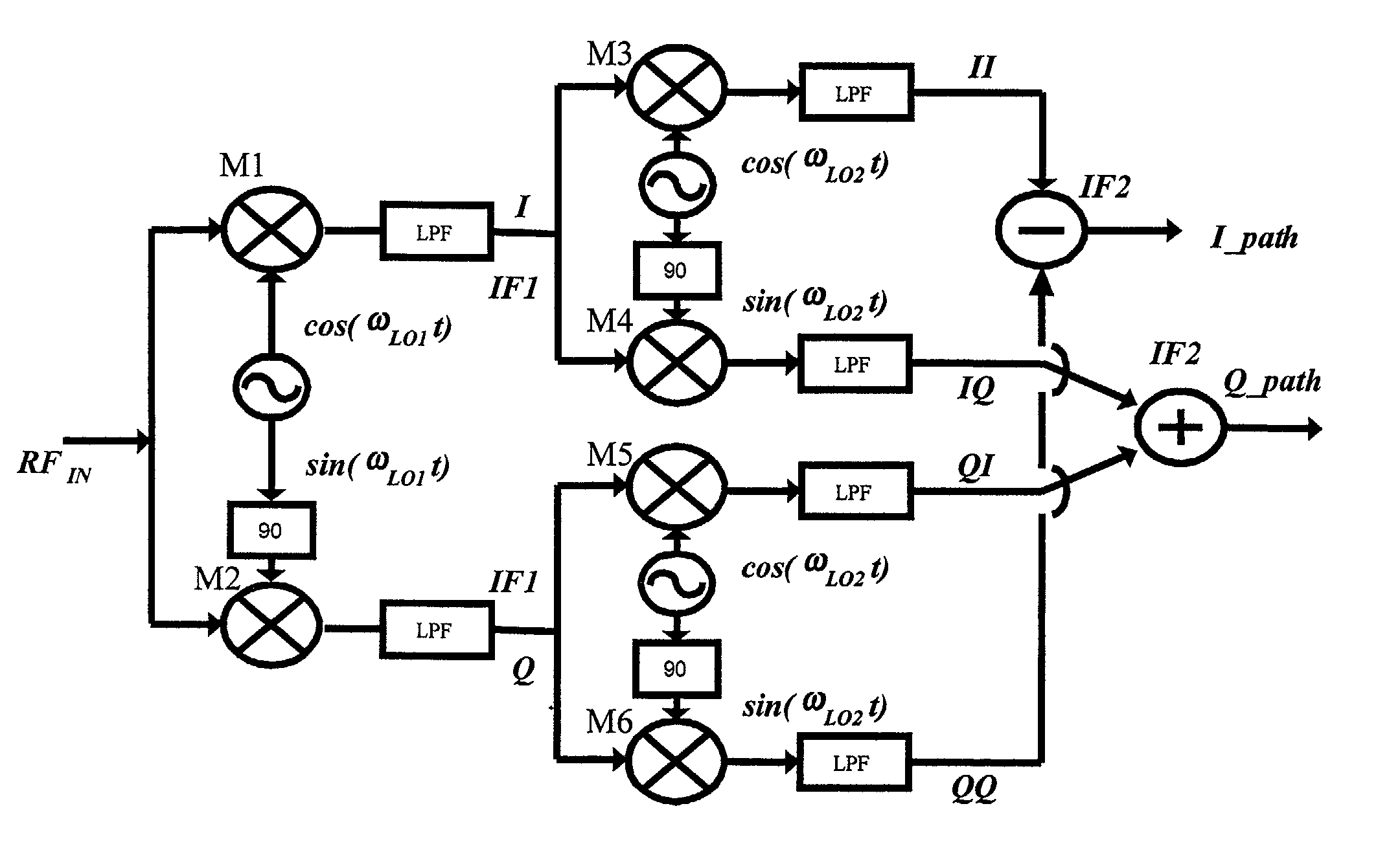
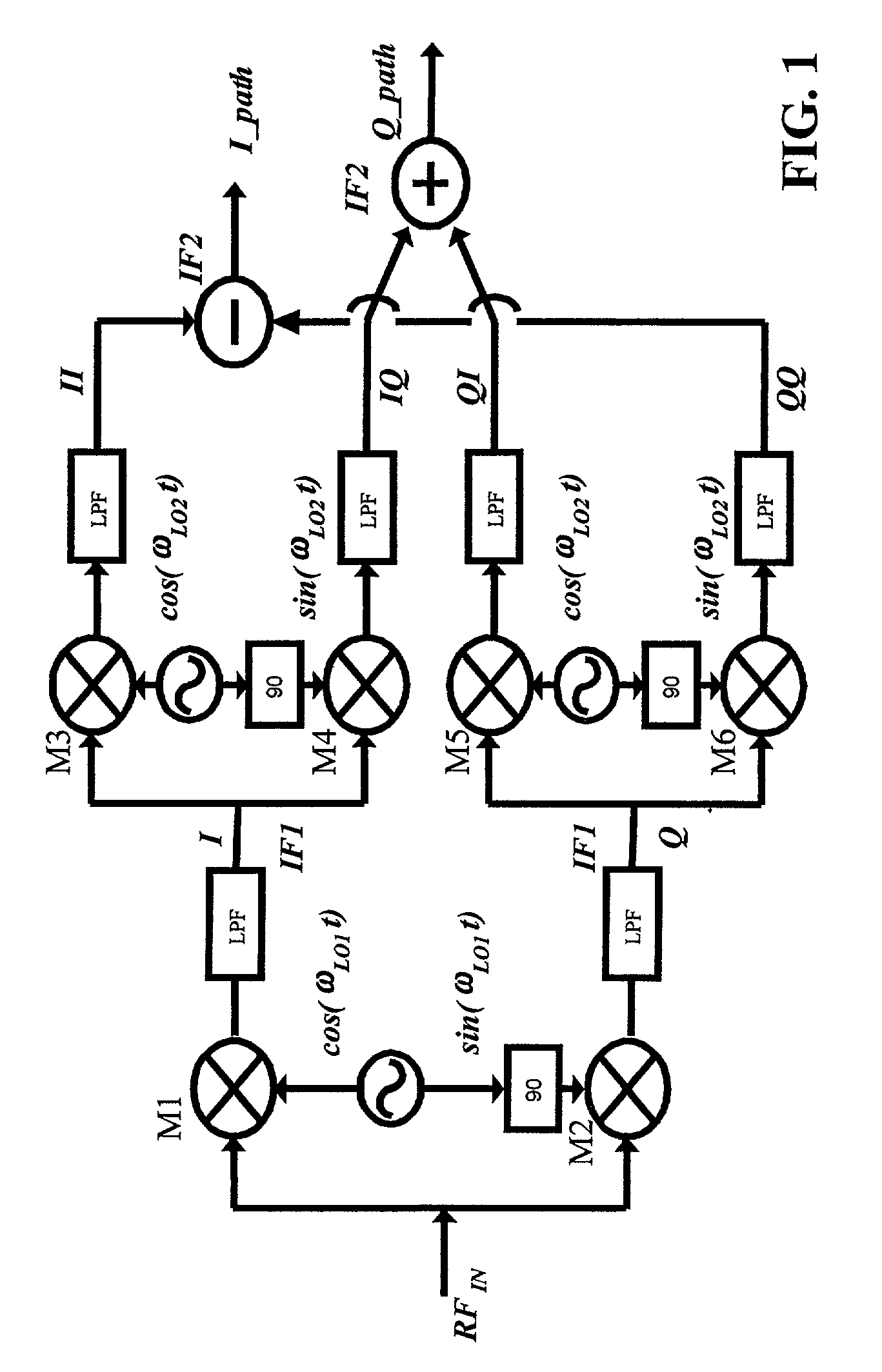
[0042]FIG. 3 shows a schematic view of a circuit diagram for illustrating a mixer according to the present invention.

[0043]As shown in FIG. 3, the mixer according to the present invention comprises an analogue circuit part and a digital circuit part.

[0044]The analogue circuit part includes mixers M1 and M2 to which input signal (RFIN) received by an antenna is input. Each output of mixers M1 and M2 is transformed into a digital signal by each of digital conversion means, e.g., analogue to digital converters (ADC), respectively.

[0045]The digital circuit part includes mixers M3 and M4 to which output of the first ADC is driven and mixers M5 and M6 to which output of the second ADC is driven. I-path signal is generated by subtracting output of mixer M3 from output of mixer M6. Q-path signal is generated by adding outputs of mixers M4 and M5. The digital ...


PUM


Abstract

An image rejection mixer (IRM) for rejecting signals having image frequency and, more particularly, a mixer for rejecting signals of image frequency by using mismatch compensation is provided. The image rejection mixer comprises: first and second mixers; first and second converting means, each of which transforms each output of the first and second mixers to digital signal; third and fourth mixers, each of which mixes output of the first converting means with each of second local oscillation in-phase signal and quadrature-phase signal, respectively; fifth and sixth mixers, each of which mixes output of the second converting means with each of second local oscillation in-phase signal and quadrature-phase signal, respectively; means for subtracting; means for adding; and means for compensating gain-mismatch between the first and second mixers.

Description

CROSS-REFERENCE TO RELATED APPLICATIONS[0001]This application claims priority under 35 U.S.C. 119(a) of Korean Patent Application Number 10-2001-0013099, entitled “IMAGE REJECTION MIXER WITH MISMATCH COMPENSATION,” filed on Mar. 14, 2001, and which is incorporated herein by reference.BACKGROUND OF THE INVENTION[0002]The present invention relates to an image rejection mixer (IRM) for rejecting signals having image frequency and, more particularly, a mixer for rejecting signals of image frequency by using mismatch compensation.[0003]In the super-heterodyne reception technique, the frequency as far as about two times of the intermediate frequency from the desired reception frequency in the frequency domain, is called the “Image Frequency.” Components having the image frequency, which is called the “Image Frequency Components” or the “Image Signal,” cause distortion of signals having intermediate frequency. Therefore, it is preferable to reject the image frequency components.[0004]In or...

Claims


Application Information

Patent Timeline
Patent Type & Authority Patents(United States)
IPC IPC(8): H04B1/18H03D7/00H03D3/00
CPCH03D3/009H03D7/18H03D2200/0066
Inventor KIM, YOUNGJINLEE, KWYRO
Owner INTEGRANT TECH
Why Eureka
Try Eureka