Wireless heart rate sensing system and method

a heart rate and sensing technology, applied in the field of sensing heart rate, can solve the problems of not being able to represent data in real-time, requiring manpower to manage equipment, and patents that fail to disclose rf system parts, etc., to achieve low noise, eliminate noise, and compact size

Inactive Publication Date: 2005-06-30
INFORMATION & COMM UNIV EDUCATIONAL FOUND
View PDF4 Cites 76 Cited by
  • Summary
  • Abstract
  • Description
  • Claims
  • Application Information

AI Technical Summary

Benefits of technology

[0014] It is an advantage of the present invention to provide a system for measuring heart rates wirelessly and representing them in real-time.
[0015] It is another advantage of the present invention to provide a heart rate measuring system with compactness of size and convenience of manipulation.
[0016] In one aspect of the present invention, a wireless heart rate sensing system comprises: an oscillator for generating signals of a specific frequency; a power divider for dividing power of the signals generated by the oscillator; a transmit antenna for radiating a first signal output by the power divider to a patient's chest; a receive antenna for receiving a signal, the frequency of which is transited by a motion of the patient's chest and which is reflected and returned; a mixer for combining frequency components of an RF signal received through the receive antenna and a second signal output by the power divider; and a baseband unit for filtering the signal combined by the mixer, converting it into a digital signal, and outputting the digital signal.
[0017] The wireless heart rate sensing system further comprises a low noise amplifier, connected between the receive antenna and the mixer, for eliminating noise from the signal received through the receive antenna, maximizing a gain, and outputting a result signal.
[0018] The transmit antenna and the receive antenna are respectively a circular polarized antenna with a different polarized component.
[0019] The transmit antenna and the receive antenna have a patch antenna format in which a cavity is provided between the two antennas on a single substrate.

Problems solved by technology

Many doctors in hospital settings measure heart rates by attaching electrodes of an ECG (electrocardiograph) meter to a human body, but this method allows measuring the heart rates only when attaching the electrodes to the body, and additionally requires manpower to manage equipment.
Further, the patent fails to disclose an RF system part but only shows a baseband part which is a signal processor.
As described, the conventional techniques apply the Doppler radar method without considering an increase of isolation or widening a dynamic range of the system in most cases, and fail to represent data in real-time since the prior art collects the measured data without further applying any skills to antennas.
Also, the conventional breath or heart rate measuring system using the Doppler radar does not consider how to widen the dynamic range (an operational range) of the system.
Therefore, it is impossible to measure the patient when he is wounded or burned at a skin area on which the electrode terminals are to be attached.

Method used


Image

  • Wireless heart rate sensing system and method
  • Wireless heart rate sensing system and method
  • Wireless heart rate sensing system and method

Examples


Embodiment Construction

[0029] In the following detailed description, only the preferred embodiment of the invention has been shown and described, simply by way of illustration of the best mode contemplated by the inventor(s) of carrying out the invention. As will be realized, the invention is capable of modification in various obvious respects, all without departing from the invention. Accordingly, the drawings and description are to be regarded as illustrative in nature, and not restrictive. To clarify the present invention, parts which are not described in the specification are omitted, and parts which have similar descriptions have the same reference numerals.

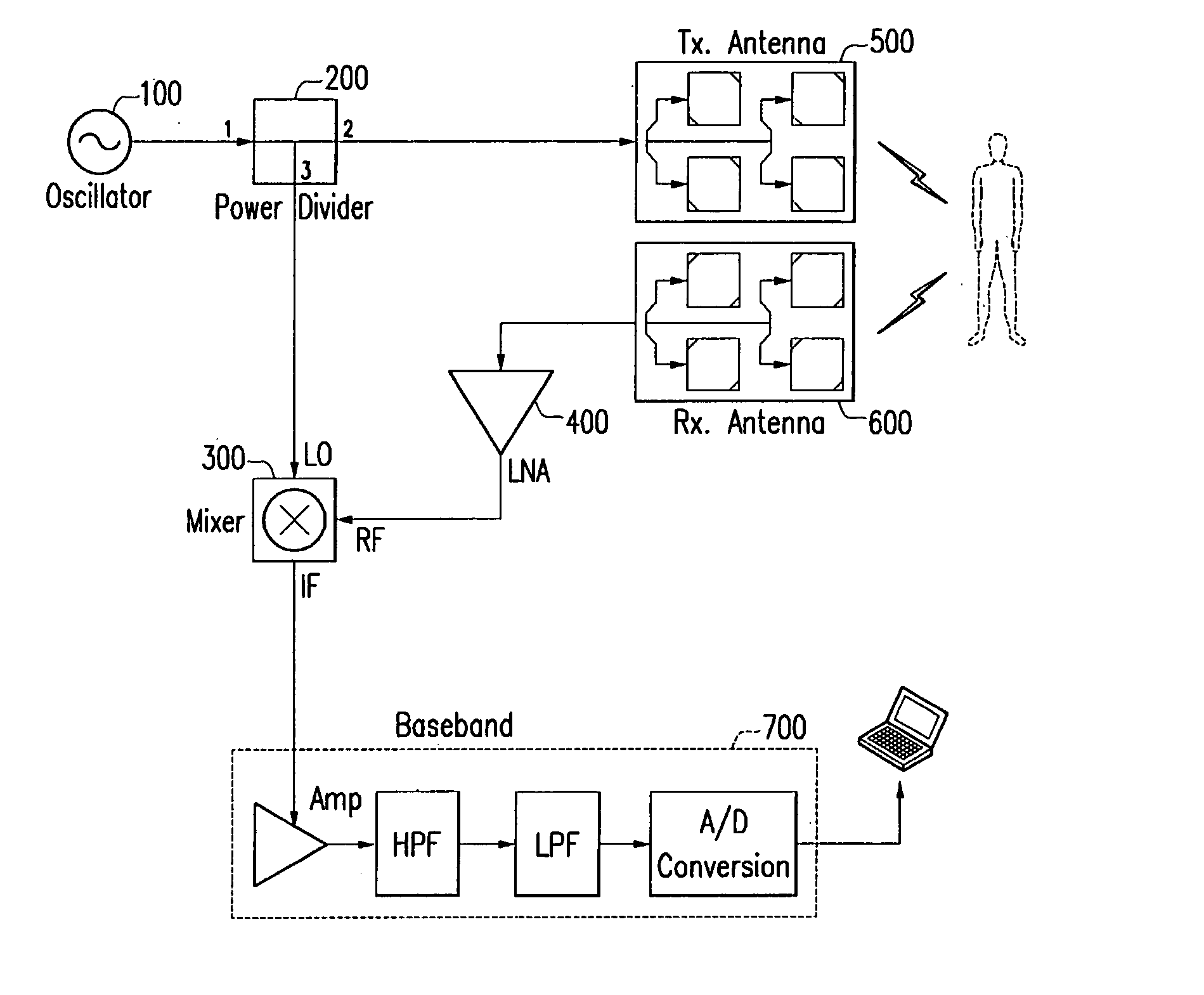
[0030] A transmit antenna and a receive antenna having two different polarized components using circular polarization are used in the preferred embodiment to increase an isolation effect compared to the conventional method for performing both transmission and receiving functions with a single antenna, thereby widening the system's dynamic range, ...


PUM


Abstract

Disclosed is a wireless heart rate sensing system which comprises: an oscillator for generating signals of a specific frequency; a power divider for dividing power of the signals generated by the oscillator; a transmit antenna for radiating a first signal output by the power divider to a patient's chest; a receive antenna for receiving a signal, the frequency of which is transited by a motion of the patient's chest and which is reflected and returned; a mixer for combining frequency components of an RF signal received through the receive antenna and a second signal output by the power divider; and a baseband unit for filtering the signal combined by the mixer, converting it into a digital signal, and outputting the digital signal.

Description

CROSS REFERENCE TO RELATED APPLICATION [0001] This application claims priority to and the benefit of Korea Patent Application No. 10-2003-97581 filed on Dec. 26, 2003 in the Korean Intellectual Property Office, the entire content of which is incorporated herein by reference. BACKGROUND OF THE INVENTION [0002] (a) Field of the Invention [0003] The present invention relates to a system for sensing heart rates. More specifically, the present invention relates to a wireless system for sensing heart rates in real-time using circular polarization. [0004] (b) Description of the Related Art [0005] Many doctors in hospital settings measure heart rates by attaching electrodes of an ECG (electrocardiograph) meter to a human body, but this method allows measuring the heart rates only when attaching the electrodes to the body, and additionally requires manpower to manage equipment. Also, patents may feel resistance since they know their heart rates are being measured during the measuring process...

Claims


Application Information

Patent Timeline
Patent Type & Authority Applications(United States)
IPC IPC(8): A61B5/0402A61B5/00A61B5/0245
CPCA61B5/0002A61B5/0507A61B5/0245
Inventor PARK, JUNG-MINKWON, YOUNG-BAEPARK, SEONG-OOK
Owner INFORMATION & COMM UNIV EDUCATIONAL FOUND
Why Eureka
Try Eureka