Non-pneumatic resilient tire

a resilient tire and non-pneumatic technology, applied in the field of vehicle wheels, can solve the problems of tire not being tire is no longer able tire is no longer able to render the service for which it is designed under good conditions, etc., to achieve good comfort, good adherence, and good capacity to transmit considerable lateral thrust

Inactive Publication Date: 2006-04-25
CONCEPTION & DEV MICHELIN SA
View PDF16 Cites 42 Cited by
  • Summary
  • Abstract
  • Description
  • Claims
  • Application Information

AI Technical Summary

Benefits of technology

[0009]The object of the present invention is to propose a non-pneumatic tire that can truly be used without inflation pressure, which will be capable, like the pneumatic tire, of bearing a substantial load while providing good comfort, go

Problems solved by technology

Although the reliability of a pneumatic tire has become remarkable, it is known that the risk of a flat is not totally eliminated.
The problem is that, in case of loss of inflation pressure, or even more insidiously in case of a substantial reduction of inflation pressure, the tire is no longer able to render the service for which it is designed under good conditions.
The proposal cited above has, however, the disadvantage that it is complicated, if not impossible, to design a tire whose sidewalls remain resilient and can tolerate suddenly mounting a curb without damage.
In fact, the reinforcing elements incorporated in the sidewalls risk being bent, in case of very marked stress, to the point that their radially outer end joins their radially inner base.
The object proposed does not therefore provide sufficient safety, since there is a strong likelihood that the tire will be destroyed (or even worse, locally degraded in a dangerous but not immediately apparent manner) by certainly extreme but not abnormal stresses (shock on a sidewalk

Method used


Image

  • Non-pneumatic resilient tire
  • Non-pneumatic resilient tire
  • Non-pneumatic resilient tire

Examples


first embodiment

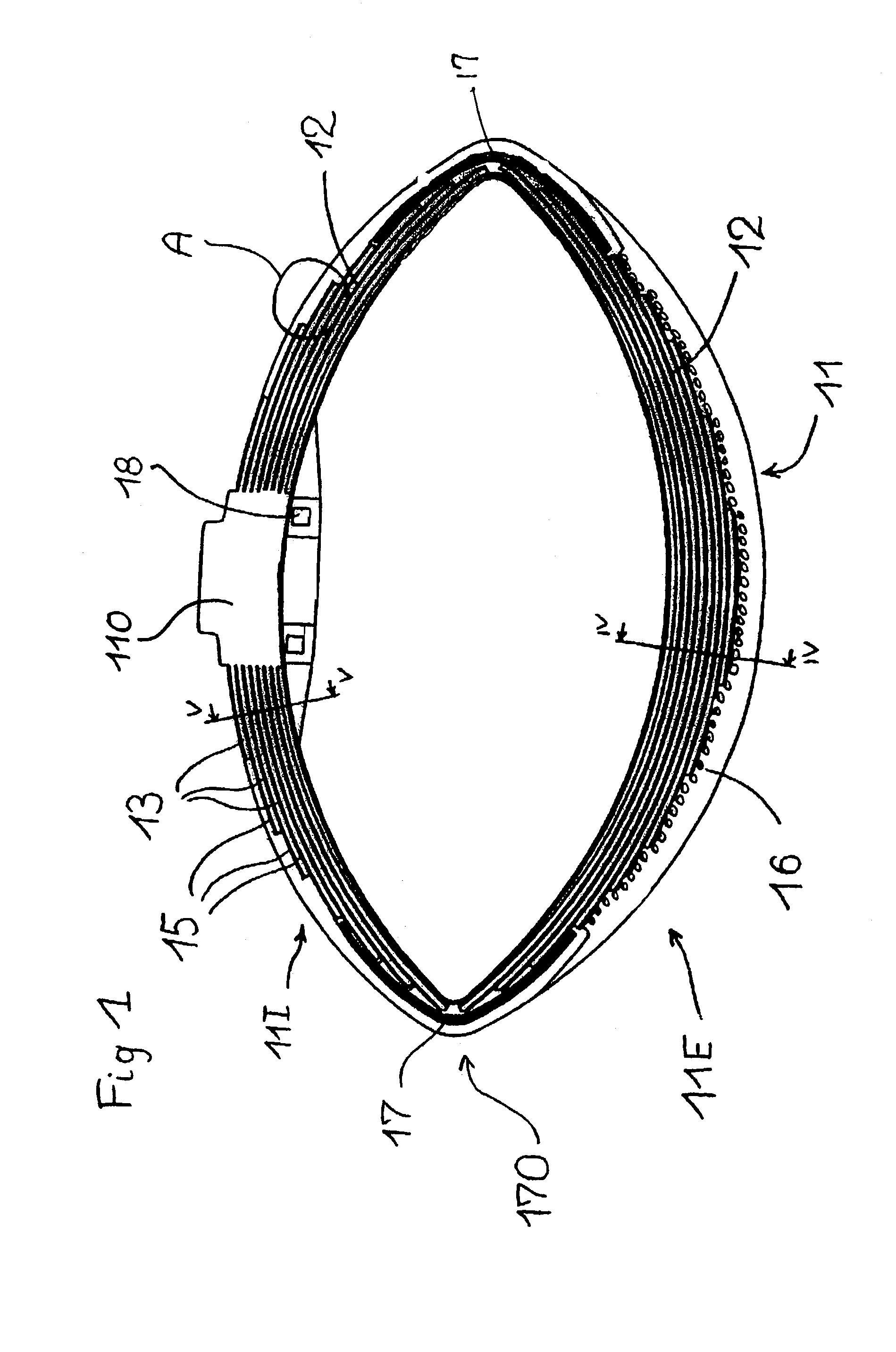
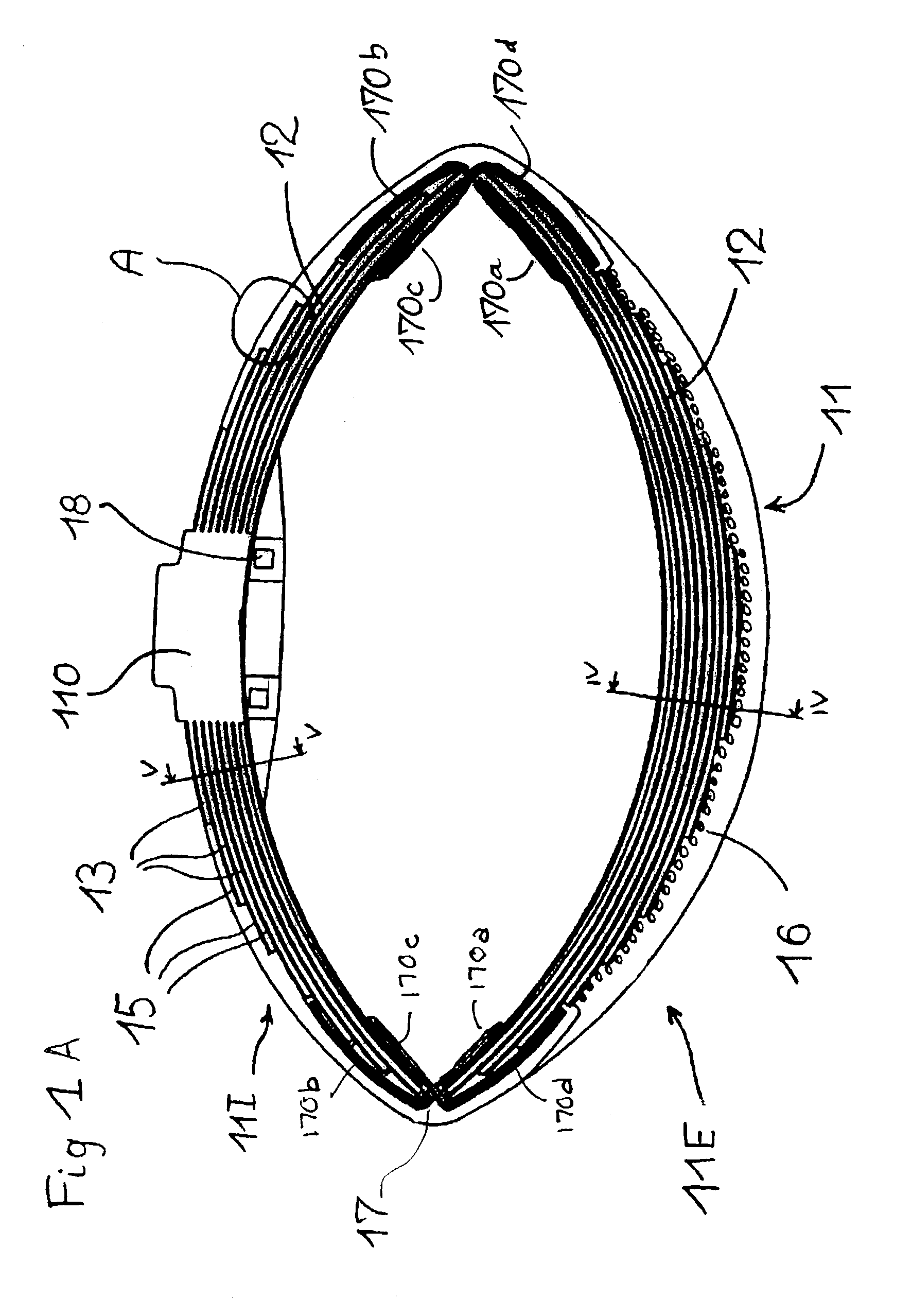
[0029]FIG. 1 shows a non-pneumatic tire having a tread 11 with a generally curved shape. The wall of the tire essentially contains two parts called “first and second structure parts 11I and 11E.” These first and second parts are radially superposed and form two springs acting in series and are respectively arranged radially inward and radially outward. One characteristic of this first embodiment is the pseudohinge separating the first 11I and second 11E structure parts, which constitutes a zone of lesser bending strength. This zone of the tire, by its constitution, does not oppose or just slightly opposes folding, that is, the relative rotation of the end parts of the first radially inner structure part and second radially outer structure part. The ends of each of the first and second bearing structure parts are situated roughly at the lateral ends of the bearing structure. The support elements consist of laminated elements 12. Each support element of the first bearing structure par...

second embodiment

[0052]The parameters of size and adjustment of properties of the non-pneumatic according to this second embodiment are, notably, those previously mentioned, namely, the thickness of layer 25 and each sheet 23, the number of sheets, the modulus of elasticity of the elastomer materials employed for the sheets, the modulus of elasticity of the elastomer used, and the arrangement of the sheets. Likewise, for the composition of the sheets 23, references should be made to the explanations supplied for sheet 13. The non-pneumatic tire also contains circumferential reinforcements (not shown) under the tread.

[0053]The non-pneumatic tire contains a tread 21, which can be very slightly bent when it is not supporting any load. The radially outer part of the bearing structure, that is, the zone containing the tread 21 and the part of the sidewalls 29 close to the tread 21, contribute only very little to deflection (radially) under the effect of the load. The sidewalls 29 and, in particular, the ...

third embodiment

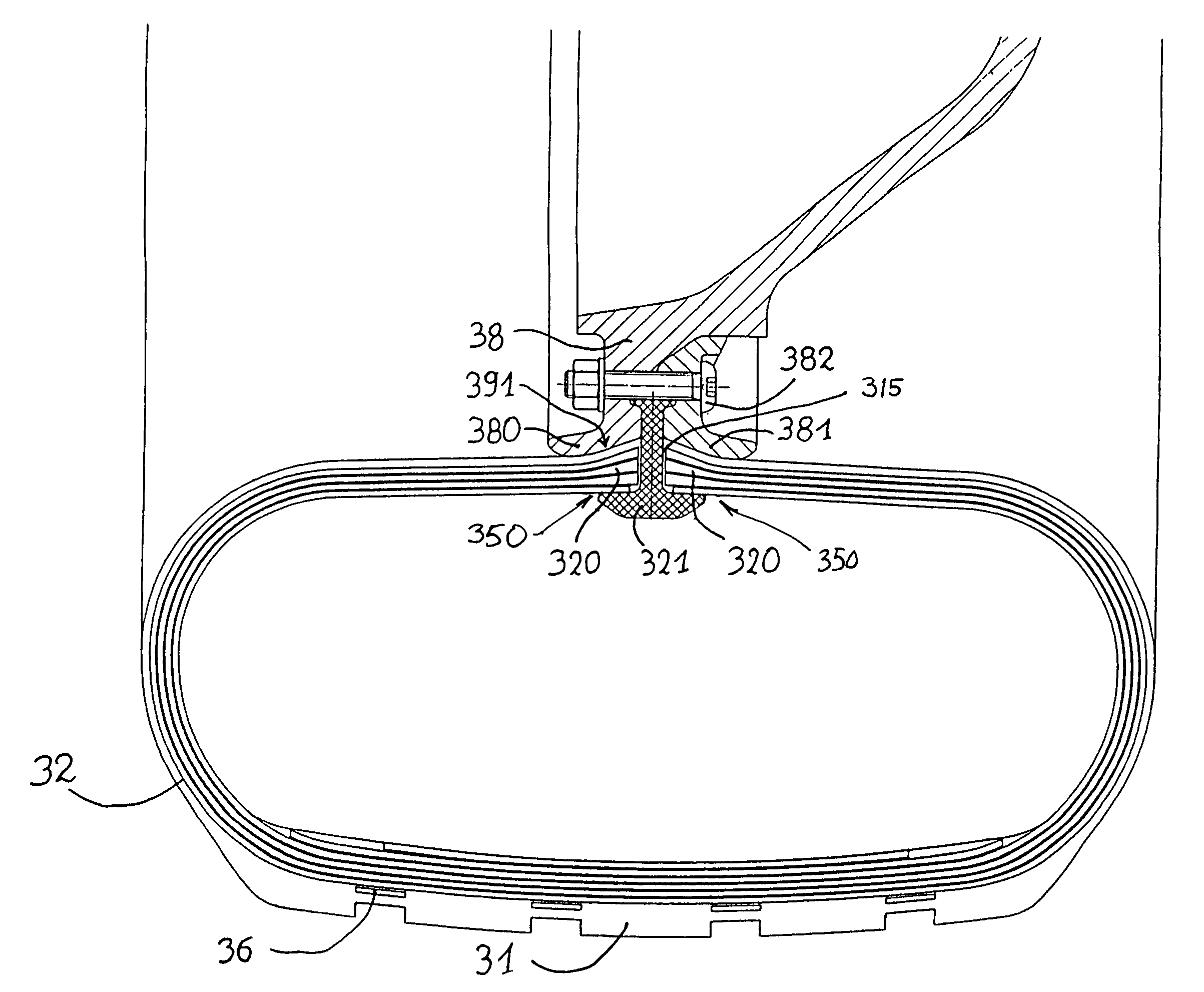
[0057]FIGS. 8 and 9 illustrate a third embodiment very similar to the second. A tread 31 and support elements 32 are provided. The interconnecting structure contains circumferential reinforcements 36 in sheet form. The zone of attachment 350 is circumferentially slotted (not shown in the simplified views of FIGS. 10 and 11), so that the non-pneumatic tire presents a slot 315 defined between two connecting ribs 320 which are capable of being axially displaced relative to each other. The connecting ribs 320 are each intended to come in contact with the means of connection to a hub, notably, through a contact bearing 391 on the radially inner side of each of the connecting ribs 320. The ribs 320 are the attachment zone 350 referred to hereinabove.

[0058]It can be seen in FIG. 8 that the latter resembles a narrow rim designed to grip the connecting ribs 320 by means of a profiled part 321 of suitable shape. As shown in FIGS. 8 and 9, the profiled part 321 extends radially through the slo...


PUM


Abstract

A non-pneumatic resilient tire which derives its capacity to bear a load from laminated elements capable of supporting bending moments. The laminated elements include a stack of resilient sheets superposed and separated by a layer of rubber adhering to the latter, forming a beam capable of undergoing bending stress.

Description

[0001]This application is a divisional application of U.S. patent application Ser. No. 09 / 466,524, filed Dec. 17, 1999, which issued as U.S. Pat. No. 6,640,859 on Nov. 4, 2003, and which claims priority from French patent application No. 98 / 16175, filed Dec. 18, 1998.BACKGROUND OF THE INVENTION[0002]The present invention concerns vehicle wheels of any type and, in particular, a non-pneumatic tire designed to be capable of bearing a load without inflation pressure.[0003]It is known that the reinforced rubber tire inflated to working pressure has come into common use, so great are its qualities of comfort and sturdiness. It has been successfully adapted to applications as different as passenger vehicles, construction equipment, airplanes, motorcycles, farm machinery, heavy trucks, etc. The inflation pressure makes it possible to bear a load and distribute it on the surface.[0004]Although the reliability of a pneumatic tire has become remarkable, it is known that the risk of a flat is ...

Claims


Application Information

Patent Timeline
IPC IPC(8): B60C7/14B60B9/04B60C3/00B60C5/00B60C7/00B60C7/10B60C7/12B60C7/16B60C15/02
CPCB60C7/10B60C7/16B60C7/12B60C7/00
Inventor LAURENT, DANIELDELFINO, ANTONIOHINC, HENRI
Owner CONCEPTION & DEV MICHELIN SA
Why Eureka
Try Eureka