

Brake assembly with tuned mass damper
a technology of mass damper and brake assembly, which is applied in the direction of shock absorbers, friction linings, mechanical apparatuses, etc., can solve the problems of excessive high pitch and undesired brake squeal noise, and achieve the effect of effective damping and less susceptible to damage when in us
- Summary
- Abstract
- Description
- Claims
- Application Information
AI Technical Summary
Benefits of technology
Problems solved by technology
Method used
Image


Examples
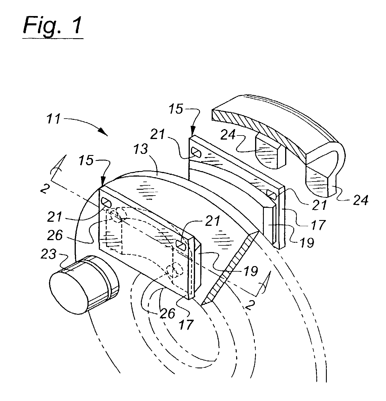
first embodiment
[0026]In the invention shown in FIG. 2, the hole 26 is blind, with a thinned section of the backplate 17 forming a bottom 30 of the hole. The hole 26 may be formed by any appropriate manufacturing method. The tuned mass damper 28 comprises a vibration damping mass 32 in the form of a small block of material such as steel and is attached directly to the hole bottom 30 by any appropriate method such as adhesive, heat or friction welding, etc. The hole bottom 30 serves as a spring member, deflecting when the backplate 17 is subjected to vibration so that the vibration damping mass 32 oscillates relative to the component. The mechanical properties of the tuned mass damper 28 are such that the most common and / or most undesirable vibration frequencies experienced by the backplate 17 excite the tuned mass damper, causing it to cancel all or part of the undesirable vibration.
second embodiment
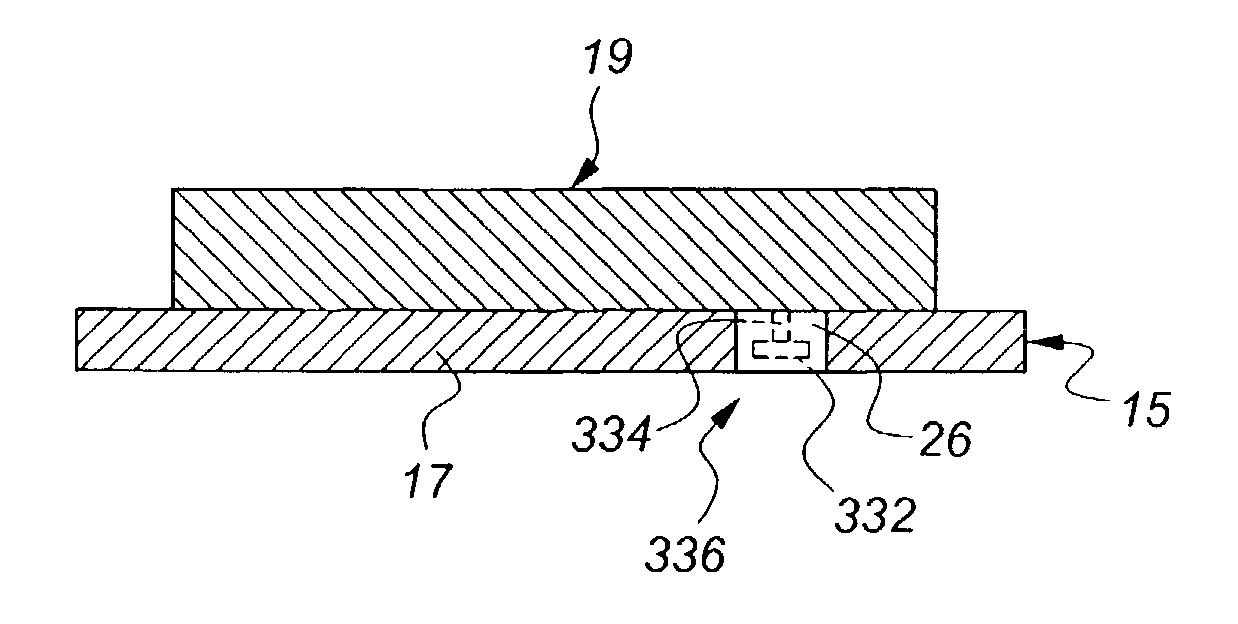
[0027]According to the invention shown in FIG. 3, the vibration damping mass 132 is attached to the hole bottom 30 by an elastic beam 134. In this embodiment, the hole bottom 30 may be thin enough such that the beam 134 and the hole bottom 30 together serve as a spring member permitting the vibration damping mass 132 to oscillate relative to the backplate 17 to cancel the unwanted vibrations. Alternatively, the hole bottom 30 may be so thick relative to the thickness of the beam 134 that the bottom 30 does not contribute significantly to the spring constant of the vibration mass damper.
third embodiment
[0028]According to the invention shown in FIG. 4, the vibration damping mass 232 is attached to an inner surface of the hole 26 by a beam 234. In this embodiment, the beam 234 serves as a spring member permitting the vibration damping mass 232 to oscillate relative to the backplate 17 to cancel the unwanted vibrations. The hole 26 may be blind, as shown in FIG. 4, or it may be a through hole.
PUM
 Abstract
Description
Claims
Application Information