
Anti-scaling device

a technology of anti-scaling and anti-scaling wires, which is applied in the direction of barbed wires, building types, construction, etc., can solve the problems of tampering with the device, unable to attach a rope, and virtually impossible for an intruder to grab hold of any part of the devi

Inactive Publication Date: 2006-04-25
MOSS FREDERICK JAMES +2
View PDF9 Cites 7 Cited by
  • Summary
  • Abstract
  • Description
  • Claims
  • Application Information

AI Technical Summary

Benefits of technology

[0006]Preferably there are pairs of spike units extending in a diametrically opposed relationship from the central body portion. It is convenient to make the spike unit separately from the body portion and to mount the spike units for rotation about radial axes extending out from the body portion. In addition serrated webs can be disposed between the spike units. This particular construction makes it virtually impossible for an intruder to grab hold of any part of the device, tamper with or attach a rope to it.

Problems solved by technology

This particular construction makes it virtually impossible for an intruder to grab hold of any part of the device, tamper with or attach a rope to it.

Method used


Image

  • Anti-scaling device
  • Anti-scaling device
  • Anti-scaling device

Examples


first embodiment

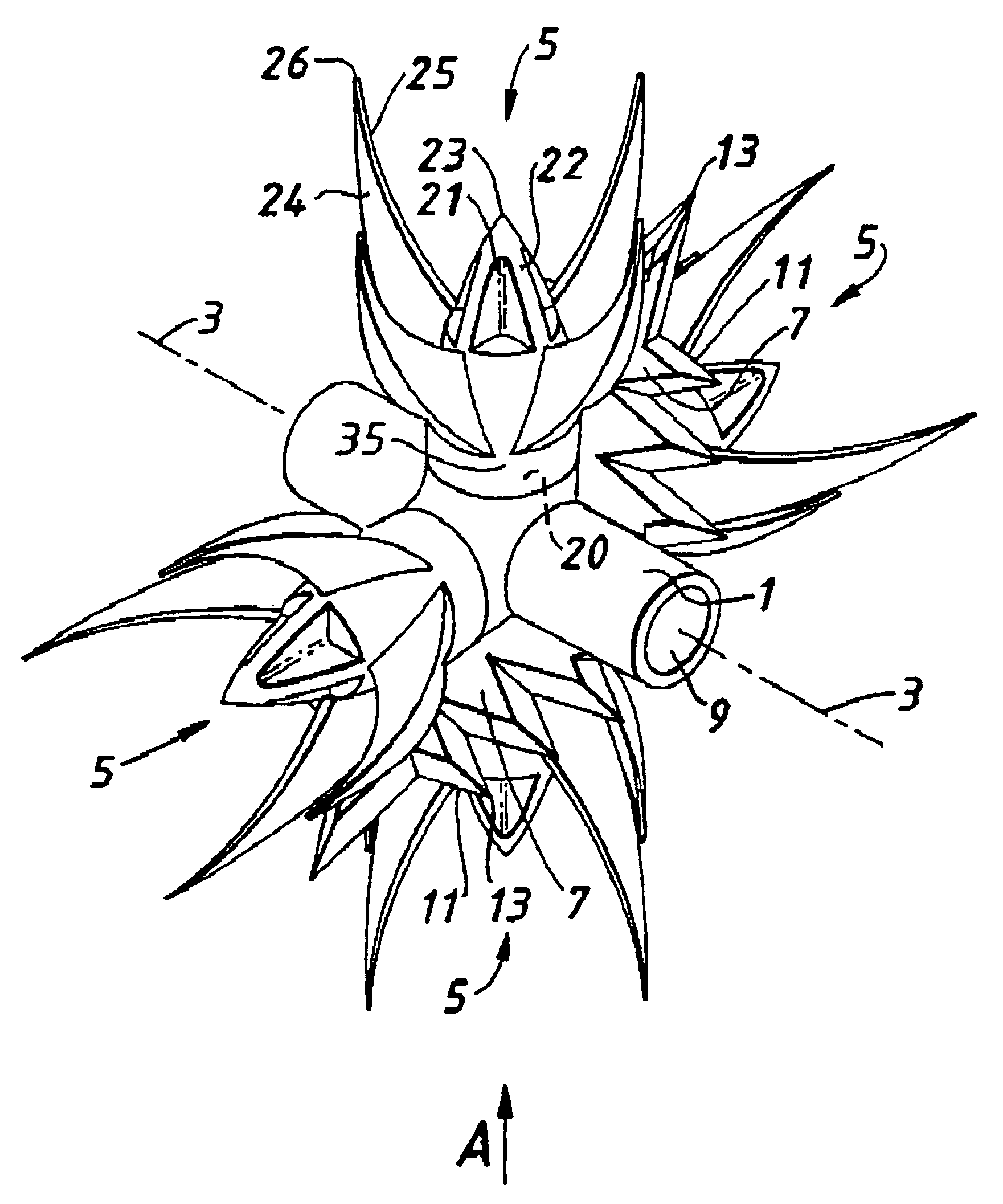
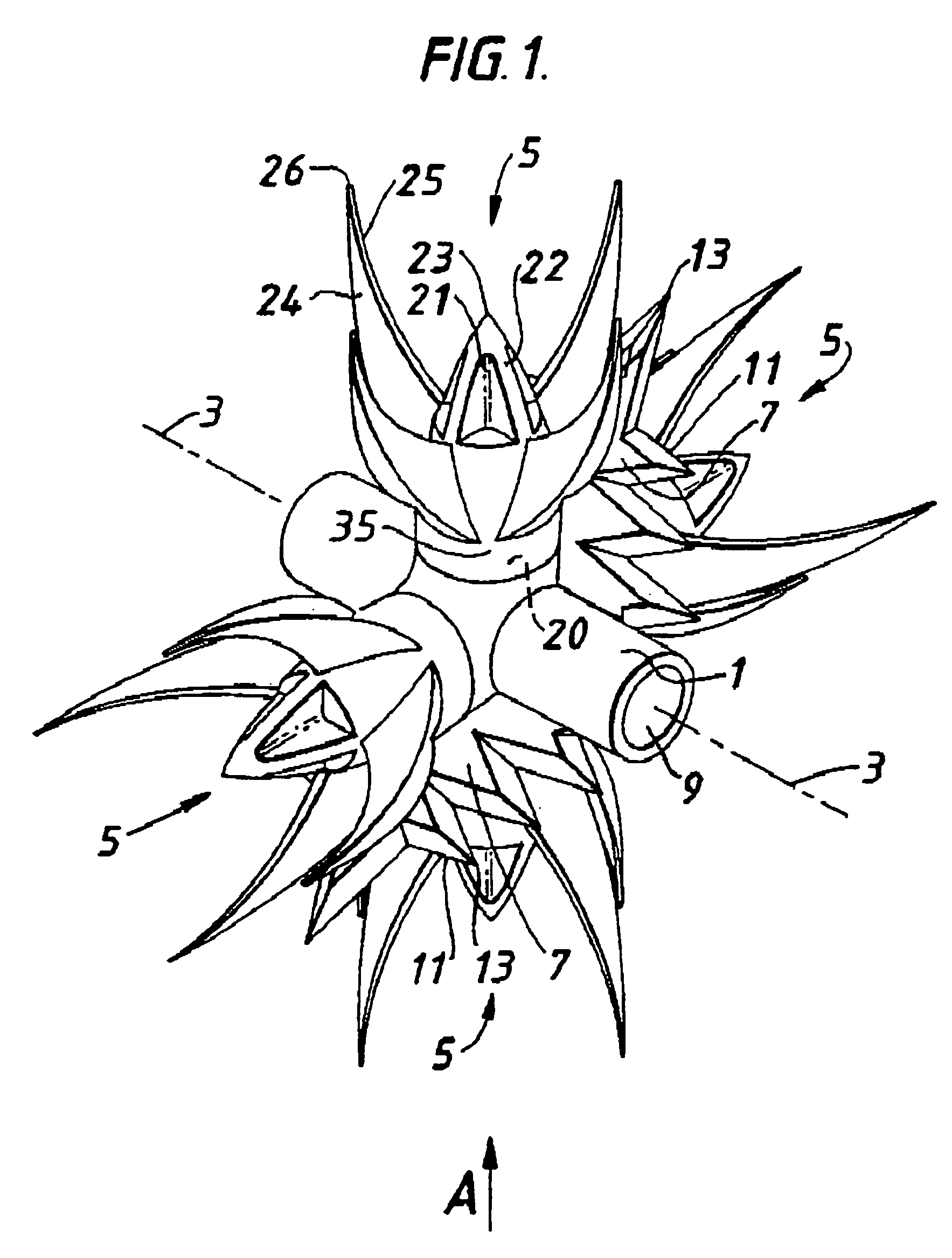
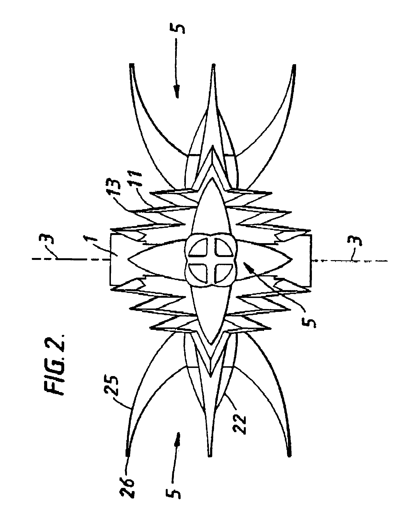
[0020]Referring to FIGS. 1, 2 and 3 the device is composed of components moulded from a suitable plastics material and comprises a hollow central body portion 1 of a generally elongate cylindrical shape with a bore 9 extending along a central transverse axis 3. Extending radially in a diametrically opposed relationship from the central body portion 1 are two pairs of spigots (not shown) upon which separate spike units 5 are detachably and rotatably mounted. Each spike unit 5 has a central boss portion 21 composed of spaced apart webs 22 which taper inwardly to an apex 23. Surrounding the central portion 21 there are four arcuate blades 24 with knife-like sharp edges 25 and a sharp tip 26. Each unit 5 has a hollow base collar 35 which fits onto one of the spigots 20. Conveniently the collar 35 may have an internal rib which snap-fits into a groove in the spigot 20 so as to retain the units 5 on the spigot 20 yet allow for rotation thereabout. Also extending radially in a diametricall...

third embodiment

[0022]FIGS. 5 and 6 show the The central body portion 1 is formed from two identical halves 17, 19. When assembled (FIG. 5) the two halves 17, 19 form two radially extending and diametrically opposed sheath units 27. These sheath units 27 each comprise a radial dagger-like serrated blade 29, two diametrically-opposed axially aligned dagger-like serrated blades 31 and two externally serrated tangential sheaths 33. The sheaths 33 each hold a serrated two-bladed propeller 37 rotatably mounted analogous to the spike units 5 of the previous embodiments. The sheaths 33 allow the propellers 37 to partially rotate backwards and forwards as indicated by the arrows 39.

[0023]FIGS. 7 and 8 illustrate the fourth embodiment. In FIG. 7 three central body portions 1 are rotatably mounted on a bar 40. Two spike units 5 are mounted on each central body portion 1 although only one is fully illustrated. The lower spike unit stem 41 represents the second spike unit in each case. As can be seen the two ...


PUM


Abstract

An anti-scaling device comprises a hollow central body for mounting on a bar and several spike units extending outwardly from the body in different directions. Pairs of spike units are rotatably and preferably detachably mounted on opposite sides of the central body. The device may further comprise serrated webs extending outwardly from the central body between the spike units. The device may also comprise rows of sharp-edged teeth axially aligned along the central body. Alternatively, the spike units may be partially rotatable serrated propellers or may be pivotably rotatably mounted. The device may be moulded from plastic material.

Description

FIELD OF INVENTION[0001]This invention relates to anti-scaling device, particularly rotary anti-sealing devices which can be positioned on top of fences, walls and gates in order to prevent potential intruders scaling such structures.DESCRIPTION OF ART[0002]Rotary anti-scaling devices generally comprise metal spike units extending from a central mounting bar or vanes of expanded metal projecting from a central rotary bar. These arrangements are prone to scaling using rope and are of relatively fragile construction. Furthermore they are relatively expensive to produce and are aesthetically unappealing.[0003]Other device consist of two identical halves of plastics material designed to connect together to form unitary spikes and be rotatably mounted on an associated bar.[0004]It is an object of the present invention to provide a more effective anti-scaling device of relatively inexpensive construction.SUMMARY OF THE INVENTION[0005]According to the present invention there is provided an...

Claims


Application Information

Patent Timeline
Patent Type & Authority Patents(United States)
IPC IPC(8): E04H17/00
CPCE04H17/003E04H17/00E04H17/004
Inventor MOSS, FREDERICK JAMESHOLLAND, JANUSZ LUCIENHUGHES, MARK CHRISTOPHER
Owner MOSS FREDERICK JAMES
Learn More