MEMS scanning mirror with tunable natural frequency

a scanning mirror and natural frequency technology, applied in the field of microelectromechanical systems, can solve the problem that minority devices do not produce the proper scanning speed

Inactive Publication Date: 2006-04-25
ADVANCED NUMICRO SYST
View PDF12 Cites 51 Cited by
  • Summary
  • Abstract
  • Description
  • Claims
  • Application Information

AI Technical Summary

Problems solved by technology

Invariably the manufacturing processes produce MEMS scanning mirrors with dimensional inconsistencies that vary the natural frequencies of the individual devices.
If the main natural frequency of a minority of the MEMS scanning mirrors is too low or too high, the minority devices will not produce the proper scan speed and the proper scan angle under an alternating current (AC) drive voltage selected for a majority of the MEMS scanning mirrors.

Method used


Image

  • MEMS scanning mirror with tunable natural frequency
  • MEMS scanning mirror with tunable natural frequency
  • MEMS scanning mirror with tunable natural frequency

Examples


Embodiment Construction

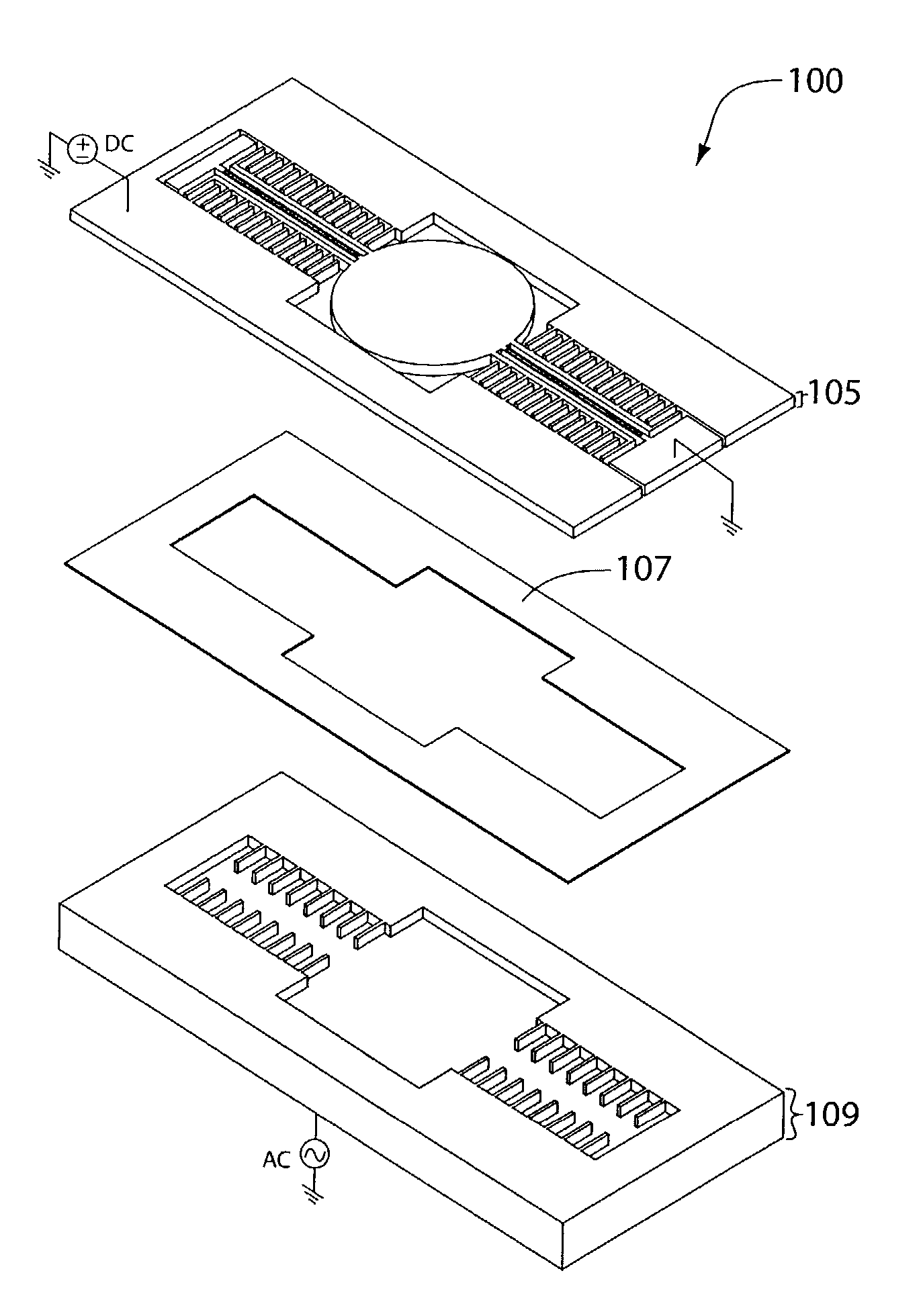
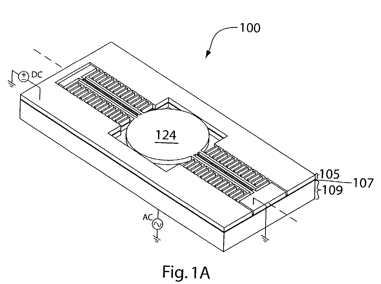
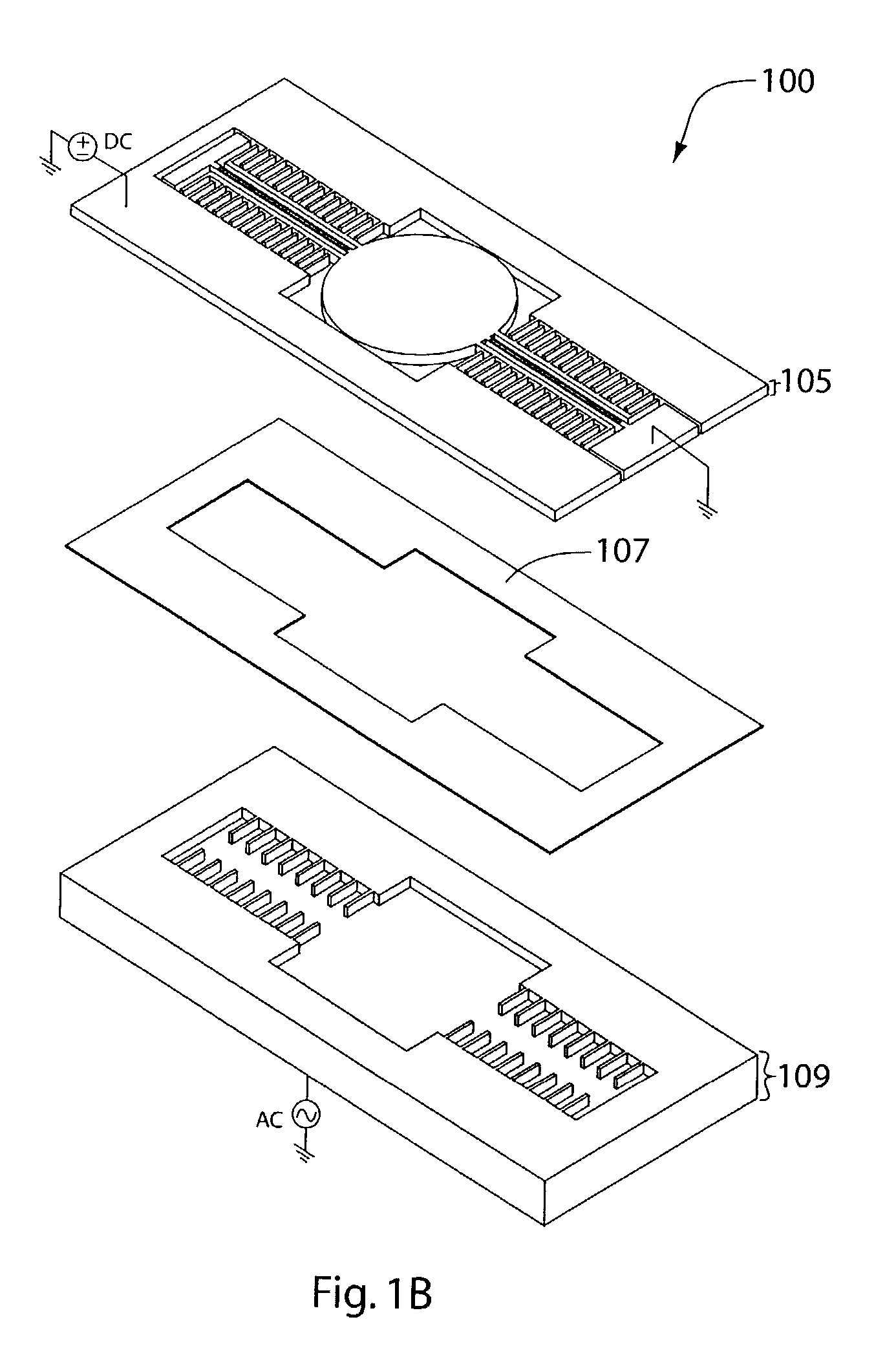
[0014]FIG. 4 illustrates a MEMS system 400 in one embodiment of the invention. MEMS system 400 includes a MEMS structure (e.g., MEMS structure 100, 200, or 300) with a mobile element that is electrostatically moved under voltages supplied by a voltage source 402. Voltage source 402 provides a voltage difference between a stationary electrode and a moving electrode of the mobile element to adjust the natural frequency of MEMS structure 100 to a desired scanning frequency. Voltage source 402 also provides an AC voltage difference between another stationary electrode and the moving electrode of the mobile element at the desired scanning frequency to oscillate the mobile element with a desired scanning angle.

[0015]The movement of the mobile element (e.g., the scanning frequency and the scanning angle) is measured by a sensor 404 and fed back to a controller 406. Controller 406 compares the measured movement to a desired movement of the mobile element and then instructs voltage source 40...


PUM


Abstract

In one embodiment of the invention, a MEMS structure includes a first electrode, a second electrode, and a mobile element. The first electrode is coupled to a first voltage source. The second electrode is coupled to a second voltage source. The mobile element includes a third electrode coupled to a third voltage source. A steady voltage difference between the first electrode and the third electrode is used to tune the natural frequency of the structure to a scanning frequency of an application. An oscillating voltage difference between the second electrode and the third electrode at the scanning frequency of the application is used to oscillate the mobile element. In one embodiment, the mobile unit is a mirror.

Description

FIELD OF THE INVENTION[0001]This invention relates to micro-electro-mechanical systems (MEMS), and more particularly to MEMS scanning mirrors.DESCRIPTION OF RELATED ART[0002]Various electrostatic designs for MEMS scanning mirrors have been proposed. Their applications include barcode readers, laser printers, confocal microscopes, fiber-optical network components, projection displays for projectors, rear projection TVs, wearable displays, and military laser tracking and guidance systems. Typically a MEMS scanning mirror is driven at its main resonance to achieve a high scan angle. Invariably the manufacturing processes produce MEMS scanning mirrors with dimensional inconsistencies that vary the natural frequencies of the individual devices. If the main natural frequency of a minority of the MEMS scanning mirrors is too low or too high, the minority devices will not produce the proper scan speed and the proper scan angle under an alternating current (AC) drive voltage selected for a m...

Claims


Application Information

Patent Timeline
Patent Type & Authority Patents(United States)
IPC IPC(8): H01L27/14G02B26/08
CPCG02B26/0841
Inventor KUO, TING-TUNG
Owner ADVANCED NUMICRO SYST
Why Eureka
Try Eureka