Surgical suturing instrument and method of use

a suturing instrument and suturing technology, applied in the field of surgical suturing instruments and methods, can solve the problems of system not providing sufficient flexibility with regard to the appropriate type of suturing stitch to be applied, device not allowing sufficient flexibility with regard to the amount of tension, system not allowing sufficient flexibility in all situations, etc., and achieves hemostasis

Inactive Publication Date: 2006-05-02
DVL ACQUISITION SUB
View PDF274 Cites 164 Cited by
  • Summary
  • Abstract
  • Description
  • Claims
  • Application Information

AI Technical Summary

Problems solved by technology

This is generally undesirable, since the needle typically leaves a larger hole in the subject than is necessary to accommodate only the suture material.
However, this device does not permit sufficient flexibility with regard to the amount of tension that may be applied to the suture and tissue.
Unfortunately, however, such a system does not permit sufficient flexibility in all situations with regard to the appropriate amount of tension to be applied to the subject, since the wire is relatively firm (i.e., firm enough to hold its sets).
Such a system also does not provide sufficient flexibility with regard to the appropriate type of suture stitch to be applied, since the device is specifically configured to provide only a spiral suture stitch.
If too much force (or tension) is applied to the suture material, then the subject portions may become necrotic or the sutures may cut through the subject.
If too little tension is applied to the suture material, then the healing process may be impaired.
Again, such a system suffers from the fact that it does not permit sufficient flexibility in all situations with regard to the appropriate tension to be applied to the subject, since the attachment is made by a staple which has a predefined geometry and is formed with relatively firm wire.
In addition, the system is limited as to the type of fastening which may be applied, since the surgical instrument is limited to only applying wire staples.

Method used


Image

  • Surgical suturing instrument and method of use
  • Surgical suturing instrument and method of use
  • Surgical suturing instrument and method of use

Examples


Embodiment Construction

Overview

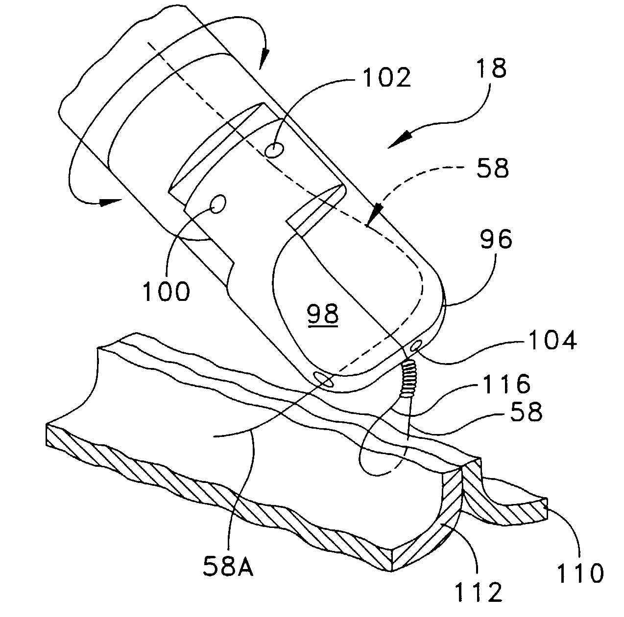
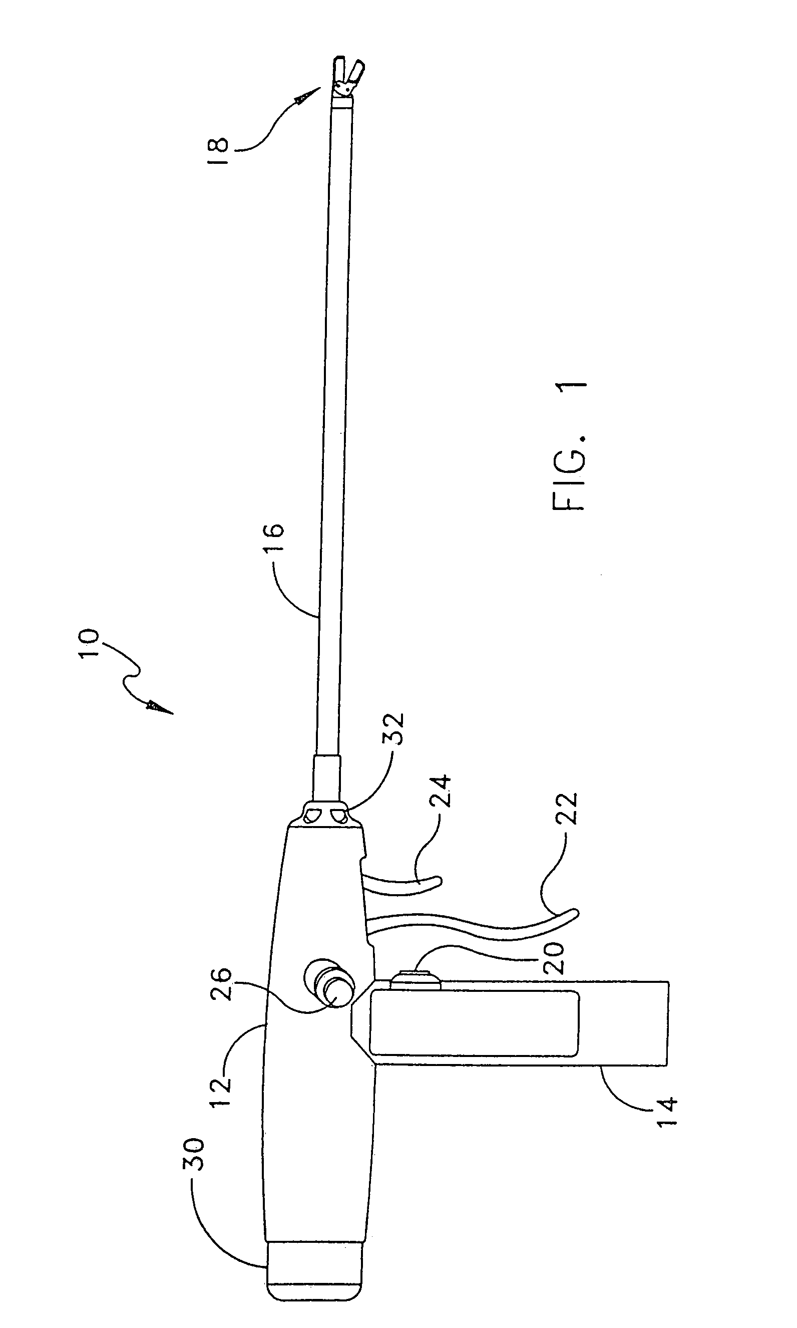
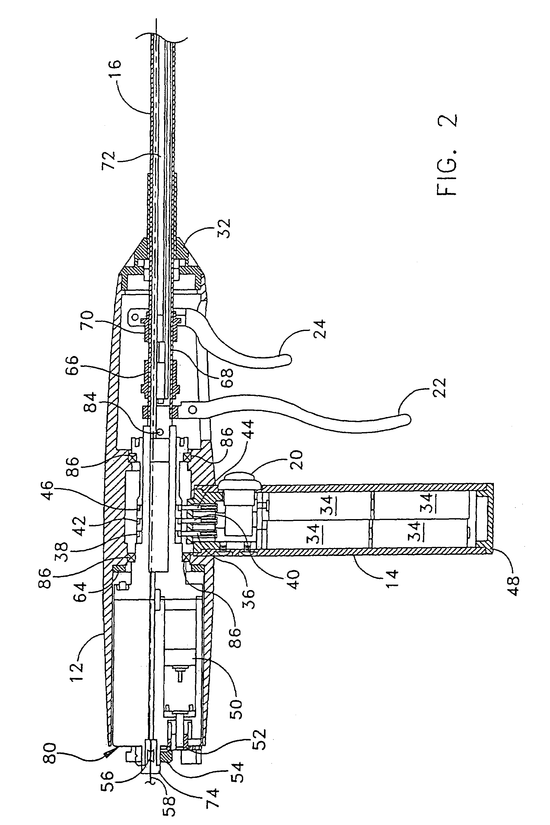
[0057]Looking first at FIG. 1, there is shown a suturing instrument 10 which comprises a preferred embodiment of the present invention. Suturing instrument 10 includes a housing 12, a handle 14, a shaft 16 and an end effector 18. Suturing instrument 10 also includes a wire advance button 20, a jaw closing actuator 22, a wire cutting actuator 24, a left-thumb-actuated rotation button 26, and a right-thumb-actuated rotation button 28 (FIG. 3). Suturing instrument 10 also includes a wire supply cartridge 30, as well as a shaft retaining nut 32. Shaft retaining nut 32 allows shaft 16 to be dismounted from the remainder of the device for cleaning purposes.

[0058]As will be discussed in further detail below, generally during use, suture wire (comprising wire formed of metal or any other suitable material having the required flexibility and stiffness) is drawn from a winding in wire supply cartridge 30 and is pushed through housing 12 and shaft 16 to end effector 18, which includes ...


PUM


Abstract

A device is disclosed for introducing a flexible elongated element through at least two portions of a subject. In an embodiment, the device includes a proximal end and a distal end, as well as an advancement unit for longitudinally advancing the flexible elongated element toward the distal end such that a distal end of the elongated element may pass from the distal end of said device with sufficient force to pass through the portions of the subject. The device also includes a securing unit for variably adjusting a securing force applied by the flexible elongated element to secure together the portions of the subject.

Description

REFERENCE TO EARLIER APPLICATIONS[0001]This is a continuation-in-part of pending prior U.S. patent application Ser. No. 10 / 014,991, filed Dec. 11, 2001 by Gregory E. Sancoff et al. for SURGICAL SUTURING INSTRUMENT AND METHOD OF USE.[0002]This patent application also claims benefit of now abandoned prior U.S. Provisional Patent Application Ser. No. 60 / 322,409, filed Sep. 14, 2001 by Frederic P. Field et al. for ENDOSCOPIC SUTURING INSTRUMENT.[0003]The two above-identified documents are hereby incorporated herein by reference.FIELD OF THE INVENTION[0004]This invention relates to medical instruments and procedures in general, and more particularly to suturing instruments and methods for suturing.BACKGROUND OF THE INVENTION[0005]Suturing instruments are typically used to draw together two or more portions of a subject patient (e.g., tissue such as muscle or skin) or to attach an object to the patient (e.g., to attach a piece of surgical mesh to the abdominal wall of the patient during h...

Claims


Application Information

Patent Timeline
Patent Type & Authority Patents(United States)
IPC IPC(8): A61B17/04A61B17/00A61B17/064A61B17/068A61B17/28
CPCA61B17/0469A61B17/0483A61B17/064A61B17/068A61B2017/2929A61B2017/00827A61B2017/0498A61B2017/0646A61B2017/00004
Inventor SANCOFF, GREGORY E.FIELD, FREDERIC P.FOGG, DOUGLAS A.DICARLO, JOSEPH A.
Owner DVL ACQUISITION SUB
Why Eureka
Try Eureka