Surface mounting type antenna, antenna apparatus and radio communication apparatus

a technology of antenna apparatus and surface mounting, which is applied in the direction of resonant antennas, substantially flat resonant elements, radiating element structural forms, etc., can solve the problems of difficult to apply surface mounting to mounting substrates, and difficult to reduce the size of surface mounting type antennas. achieve the effect of satisfying antenna characteristics and convenient frequency adjustmen

Inactive Publication Date: 2006-05-02
KYOCERA CORP
View PDF8 Cites 17 Cited by
  • Summary
  • Abstract
  • Description
  • Claims
  • Application Information

AI Technical Summary

Benefits of technology

[0051]As described above, according to the invention, it is possible to provide a surface mounting type antenna applicable to two frequencies with which satisfactory antenna characteristics can be obtained stably and frequency adjustment can be performed easily, and a size of which can be reduced, and an antenna apparatus using this surface mounting type antenna. In addition, it is possible to provide a radio communication apparatus applicable to two frequencies including the surface mounting type antenna and the antenna apparatus applicable to two frequencies.

Problems solved by technology

However, in the conventional surface mounting type antenna 61 shown in FIG. 4, there is a problem that, in order to match an operation frequency of the surface mounting type antenna 61 to a lower frequency f1 and a higher frequency f2 of a radio signal used in a communication system, it is necessary to adjust lengths and pitches of the spiral radiation electrodes 62 and 63, and the adjustment requires many labor hours.
In addition, there is also a problem that, when it is attempted to increase a dielectric constant of the base body 66 to reduce a size of the surface mounting type antenna 61, since an unnecessary resonance mode occurs unexpectedly between the spiral long radiation electrodes 62 and 63 and the ground conductor layer 73, and stable antenna characteristics applicable to two frequencies is not obtained, it is difficult to reduce a size of the surface mounting type antenna 61.
Further, in the antenna for a mobile communication terminal disclosed in JP-A 2002-204120, there is a problem that it is difficult to apply surface mounting to a mounting substrate.
Moreover, in the antenna apparatus disclosed in JP-A-2002 314330, there is a problem that since the radiation electrodes have a plane pattern, a size of the antenna increases, and it is difficult to reduce a size of the antenna.

Method used


Image

  • Surface mounting type antenna, antenna apparatus and radio communication apparatus
  • Surface mounting type antenna, antenna apparatus and radio communication apparatus
  • Surface mounting type antenna, antenna apparatus and radio communication apparatus

Examples


first embodiment

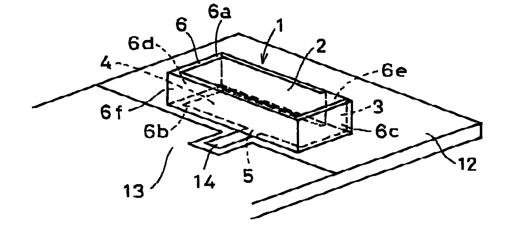
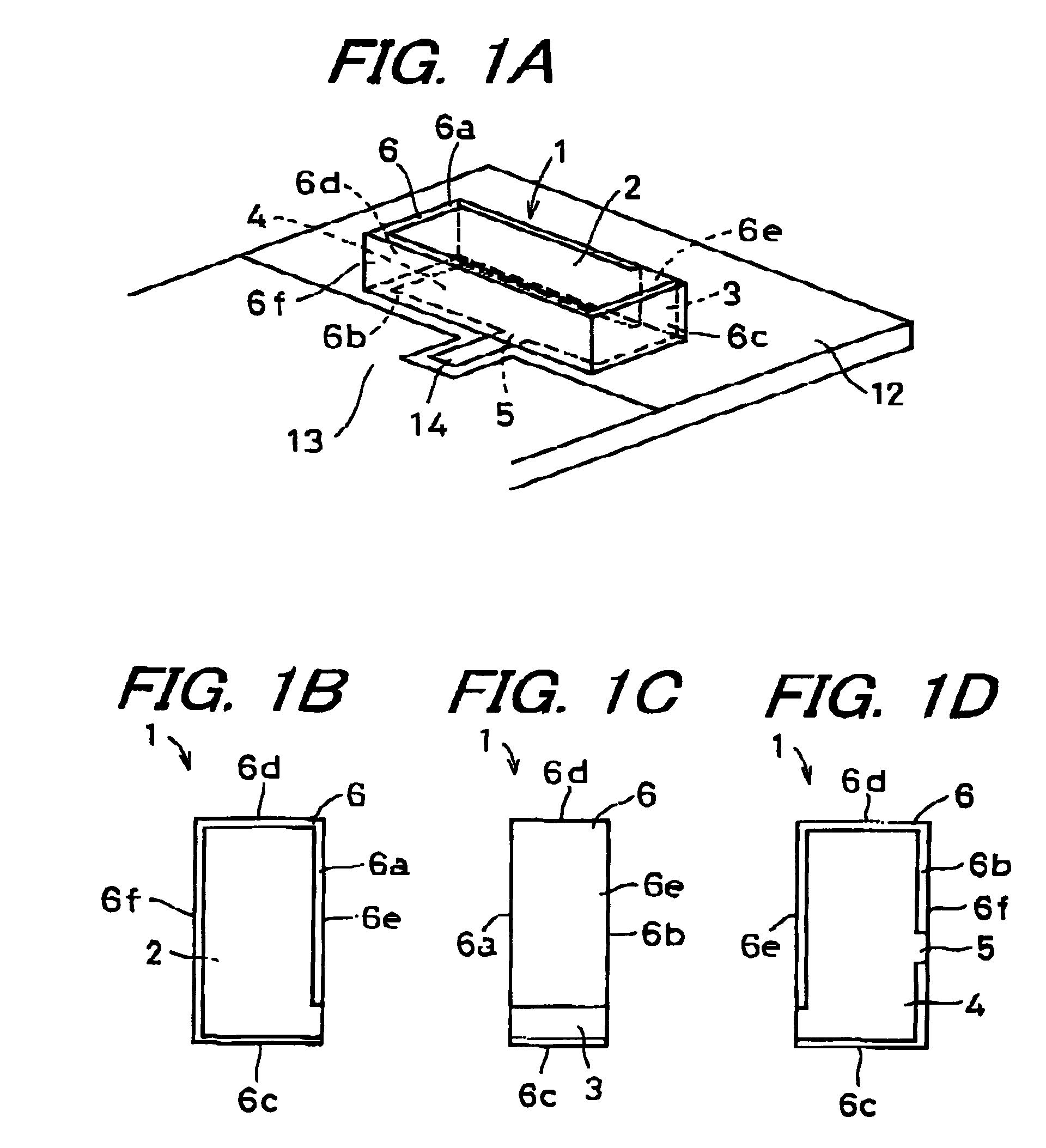
[0072]A surface mounting type antenna 1 according to the invention includes a base body 6, a first radiation electrode 2, a second radiation electrode 4, a third radiation electrode 3 and a feeder terminal 5. The base body 6 is made of dielectric or magnetic material and is formed in a rectangular parallelepiped shape. The base body 6 includes a first pair of side faces 6a and 6b opposed to each other, a pair of end faces 6c and 6d opposed to each other and a second pair of side faces 6e and 6f opposed to each other. The first radiation electrode 2 is formed on one side face (i.e., an upper face of the base body 6 in FIG. 1A) 6a of the first pair of side faces 6a and 6b so as to extend from one end face 6c side to another end face 6c side thereof. The second radiation electrode 4 is formed on another side face (i.e., a lower face of the base body 6 in FIG. 1A) 6b of the first pair of side faces 6a and 6b so as to extend from the one end face 6c side to the other side face 6d side th...

second embodiment

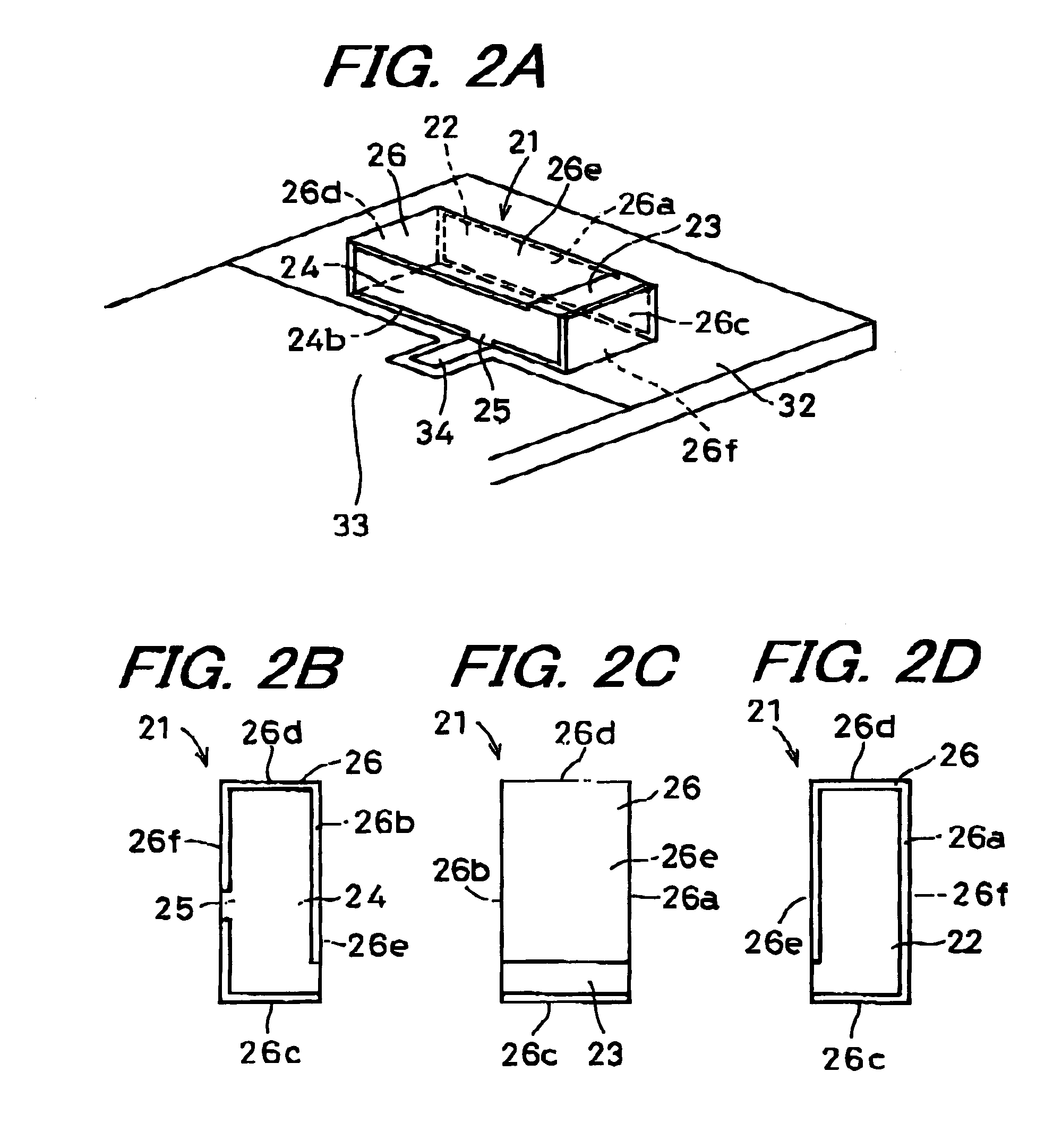
[0085]A surface mounting type antenna 21 according to the invention includes a base body 26, a first radiation electrode 22, a second radiation electrode 24, a third radiation electrode 23 and a feeder terminal 25. The base body 26 is made of dielectric or magnetic material and is formed in a rectangular parallelepiped shape. The base body 26 includes a first pair of side faces 26a and 26b opposed to each other, a pair of end faces 26c and 26d opposed to each other and a second pair of side faces 26e and 26f opposed to each other. The first radiation electrode 22 is formed on one side face (i.e., a side face on a far side of the base body 26 in FIG. 2A) 26a of the first pair of side faces 26a and 26b so as to extend from one end face 26c side to another end face 26c side thereof. The second radiation electrode 24 is formed on another side face (i.e., a side face on a near side of the base body 26 in FIG. 2A) 26b of the first pair of side faces 26a and 26b so as to extend from the on...

third embodiment

[0091]A surface mounting type antenna 41 according to the invention includes a base body 46, a first radiation electrode 42, a second radiation electrode 44, a third radiation electrode 43 and a feeder terminal 45. The base body 46 is made of dielectric or magnetic material and is formed in a rectangular parallelepiped shape. The base body 46 includes a first pair of side faces 46a and 46b opposed to each other, a pair of end faces 46c and 46d opposed to each other and a second pair of side faces 46e and 46f opposed to each other. The first radiation electrode 42 is formed on one side face (i.e., a side face on a far side of the base body 46 in FIG. 3A) 46a of the first pair of side faces 46a and 46b so as to extend from one end face 46c side to another end face 46c side thereof. The second radiation electrode 44 is formed on another side face (i.e., a side face on a near side of the base body 46 in FIG. 3A) 26b of the first pair of side faces 46a and 46b so as to extend from the on...


PUM


Abstract

The surface mounting type antenna includes a rectangular parallelepiped base body, a group of radiation electrodes and a feeder terminal. The group of radiation electrodes includes radiation electrodes formed on a first pair of side faces so as to extend from one end face side to another end face side thereof, and a radiation electrode formed on the one end face side of one side face of a second pair of side faces, the radiation electrode being connected to the radiation electrodes formed on the first pair of side faces. The feeder terminal is formed on a part of another side face of the first pair of side faces, the part being in a vicinity of another side face of the second pair of side faces, the feeder terminal being connected to the group of radiation electrodes.

Description

BACKGROUND OF THE INVENTION[0001]1. Field of the Invention[0002]The present invention relates to a surface mounting type antenna which is a small-sized antenna applicable to two frequencies used in a mobile communication apparatus such as a cellular phone, an antenna apparatus, and a radio communication apparatus using the surface mounting type antenna and the antenna apparatus.[0003]2. Description of the Related Art[0004]Reduction in size for a mobile communication apparatus such as a cellular phone has been advanced rapidly. Concerning an antenna that is a component of the mobile communication apparatus, efforts have been made to cope with the reduction in size using a surface mounting type antenna and the like. An example of a conventional surface mounting type antenna and an antenna apparatus using the surface mounting type antenna will be explained with reference to a perspective view of FIG. 4.[0005]In FIG. 4, reference numeral 61 denotes a surface mounting type antenna, which...

Claims


Application Information

Patent Timeline
Patent Type & Authority Patents(United States)
IPC IPC(8): H01Q1/24H01Q13/08H01Q1/38H01Q5/10H01Q9/04
CPCH01Q1/243H01Q9/0442H01Q9/0407H01Q1/38
Inventor IKUTA, TAKANORISATO, AKINORI
Owner KYOCERA CORP
Why Eureka
Try Eureka