Foldable portable radio device

a portable radio and antenna technology, applied in the direction of substation equipment, antenna details, antennas, etc., to achieve the effect of reducing loss and satisfying antenna characteristics

Inactive Publication Date: 2012-07-03
NEC CORP
View PDF10 Cites 1 Cited by
  • Summary
  • Abstract
  • Description
  • Claims
  • Application Information

AI Technical Summary

Benefits of technology

[0005]It is an object of the present invention to provide a foldable portable radio device which is capable of solving the problem inherent to the background art. An example of the object is to provide a portable radio device which is capable of alleviating a loss due to mutual coupling between antennas and exhibiting satisfactory antenna characteristics in a foldable portable radio device which comprises a radio communication antenna and a digital television reception antenna, which are mounted in close proximity to each other near a hinge section.

Problems solved by technology

Further, when a digital television reception antenna is added to this type of radio device, a telescopic whip antenna is often mounted near the hinge section, with the result that the antennas are in close proximity to each other.
A loss due to mutual coupling, and the like are envisaged in recent portable radio devices which are desired to be increasingly reduced in size, whereas in portable radio devices capable of receiving digital television, a radio wave emitted from a radio communication antenna can be absorbed by a digital television reception antenna, arranged in close proximity thereto, to cause a loss.
However, considering a scenario where a small portable radio device is used near a human body, particularly when held by a hand, this solution is not advisable because a loss due to a human body is a concern for either of the antennas if the antenna is mounted in a lower end region of a housing, where the antenna is more likely to be grasped.

Method used


Image

  • Foldable portable radio device
  • Foldable portable radio device
  • Foldable portable radio device

Examples


embodiment 1

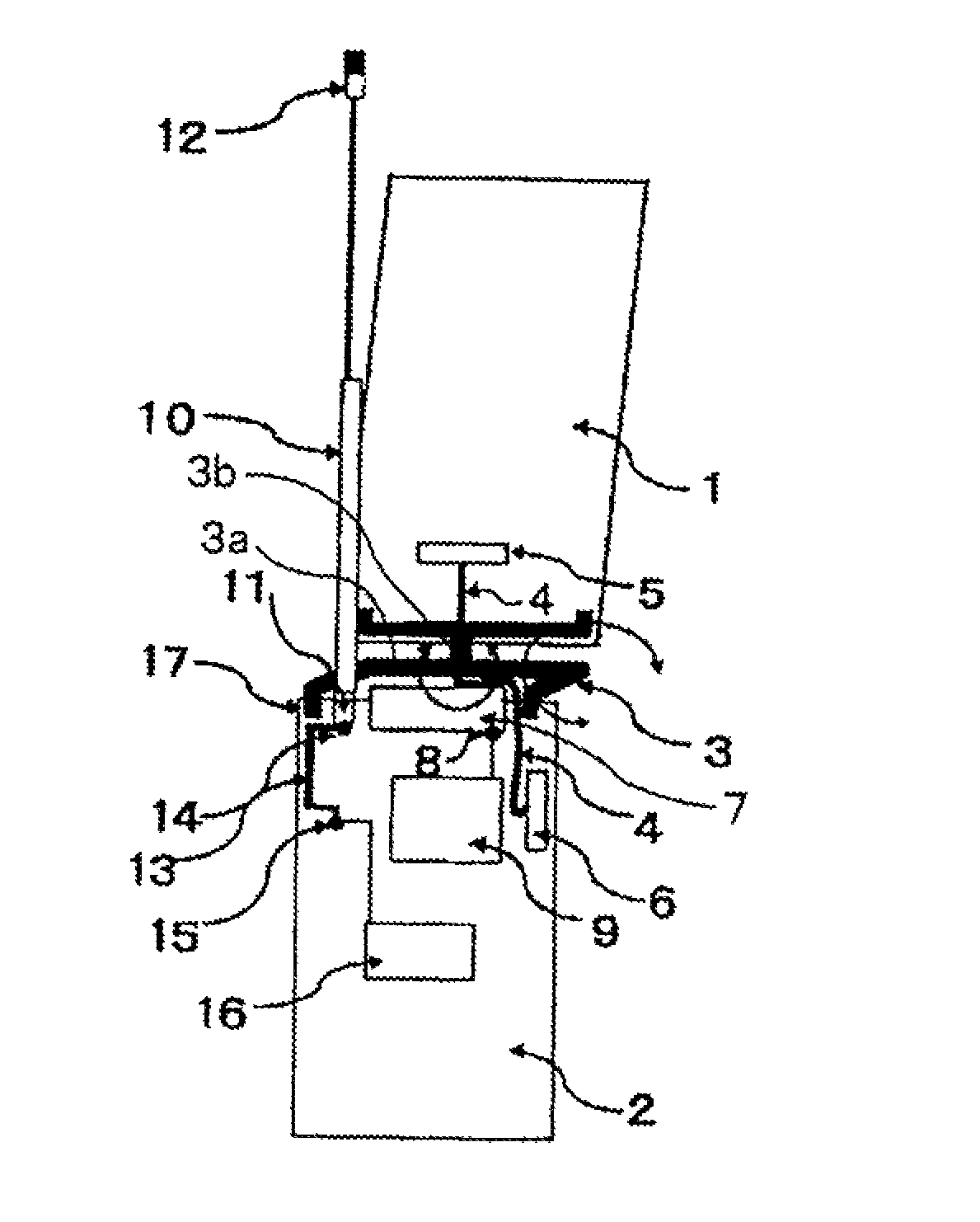
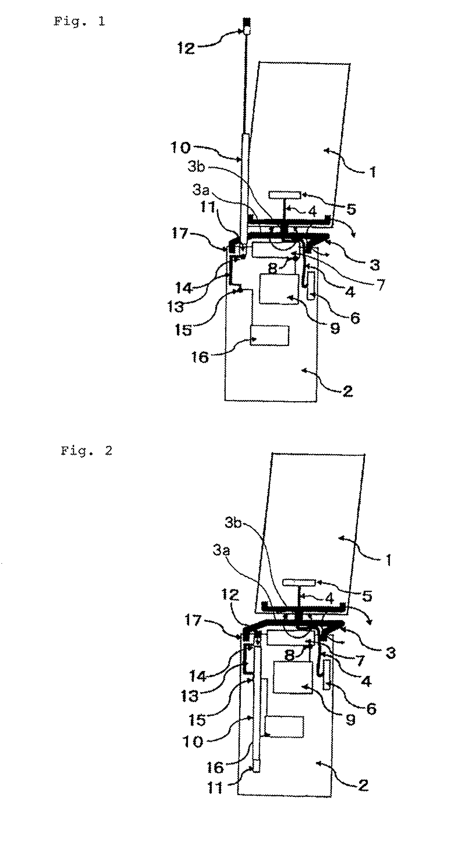
[0018]FIGS. 1 and 2 are schematic diagrams of a portable radio device according to Embodiment 1 of the present invention, showing a state where an upper housing is opened with respect to a lower housing by a hinge section of the portable radio device.

[0019]In these figures, the portable radio device comprises an upper housing (not shown) which contains upper board 1, and a lower housing which contains lower board 2, and ends of upper board 1 and lower board 2 are coupled to each other by biaxial hinge fitting 3.

[0020]Specifically, first shaft 3a of biaxial hinge fitting 3 is arranged in a coupling end with the lower board 2 on upper board 1, second shaft 3b is arranged perpendicularly to and for rotation relative to this first shaft 3a, and a coupling end with upper board 1 on lower board 2 is rotatably attached to this second shaft 3b. In this way, the upper housing and lower housing can be opened / closed about first shaft 3a of biaxial hinge fitting 3 from a state in which they lie...

embodiment 2

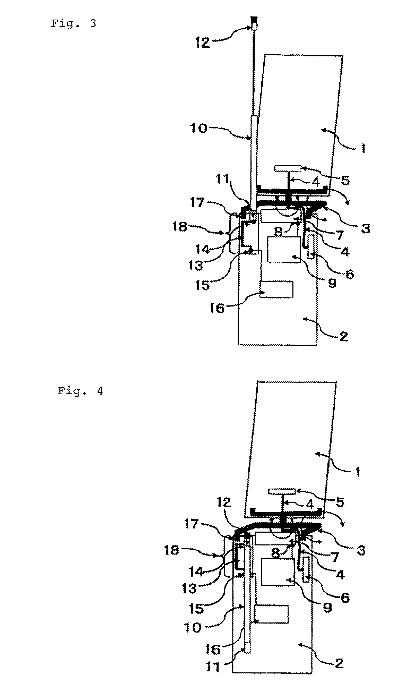
[0039]FIGS. 3 and 4 are schematic diagrams of a portable radio device according to Embodiment 2 of the present invention, showing a state where an upper housing is opened with respect to a lower housing by a hinge section of the portable radio device. Specifically, FIG. 3 shows a state where digital television reception antenna 10 is drawn out from a lower housing. FIG. 4 shows a state where digital television reception antenna 10 is retracted in the lower housing.

[0040]The following description will be given of parts different from the configuration of Embodiment 1. In this regard, the same reference numerals are used for the same components as those in Embodiment 1 in FIGS. 3 and 4, and descriptions thereon are omitted.

[0041]In this embodiment, in addition to the configuration described in Embodiment 1, a peripheral portion close to auxiliary pattern 13 is removed from a ground section of lower board 2. Stated another way, auxiliary pattern 13 is arranged in ground free section 18...


PUM


Abstract

A foldable portable radio device comprises a first housing, a second housing, a hinge section for coupling the first and second housings such that the radio device is foldable, a radio communication antenna built in a region of the first or second housing near the hinge section, and a digital television reception whip antenna which can be retracted into and drawn out from the region near the hinge section where the radio communication antenna is built in. The foldable portable radio device also comprises a function for powering the digital television reception whip antenna through an electric connection pattern, wherein the electric connection pattern is formed in a direction away from the region near the hinge section where the radio communication antenna is built in.

Description

[0001]This application is the National Phase of PCT / JP2008 / 063103, filed Jul. 22, 2008, which claims the priority based on Japanese Patent Application 2007-208270 filed Aug. 9, 2007, the disclosure of which is incorporated herein by reference in its entirety.TECHNICAL FIELD[0002]The present invention relates to a foldable portable radio device which comprises a radio communication antenna and a digital television reception antenna.BACKGROUND ART[0003]In conventional foldable portable radio devices, a multi-band supporting built-in antenna is often arranged near a hinge section of a foldable housing. Further, when a digital television reception antenna is added to this type of radio device, a telescopic whip antenna is often mounted near the hinge section, with the result that the antennas are in close proximity to each other.[0004]A loss due to mutual coupling, and the like are envisaged in recent portable radio devices which are desired to be increasingly reduced in size, whereas i...

Claims


Application Information

Patent Timeline
Patent Type & Authority Patents(United States)
IPC IPC(8): H01Q1/24
CPCH01Q1/243H01Q1/244H01Q1/521H01Q21/28
Inventor IDE, YOSHIYUKI
Owner NEC CORP
Why Eureka
Try Eureka