Method and apparatus for calculating an operator distraction level

a technology of operator distraction and calculation method, applied in the field of collision warning system, can solve the problems of increasing the driver distraction level and lowering their safety, and achieve the effect of facilitating a threat assessment decision

Inactive Publication Date: 2006-05-02
HRL LAB
View PDF13 Cites 29 Cited by
  • Summary
  • Abstract
  • Description
  • Claims
  • Application Information

AI Technical Summary

Benefits of technology

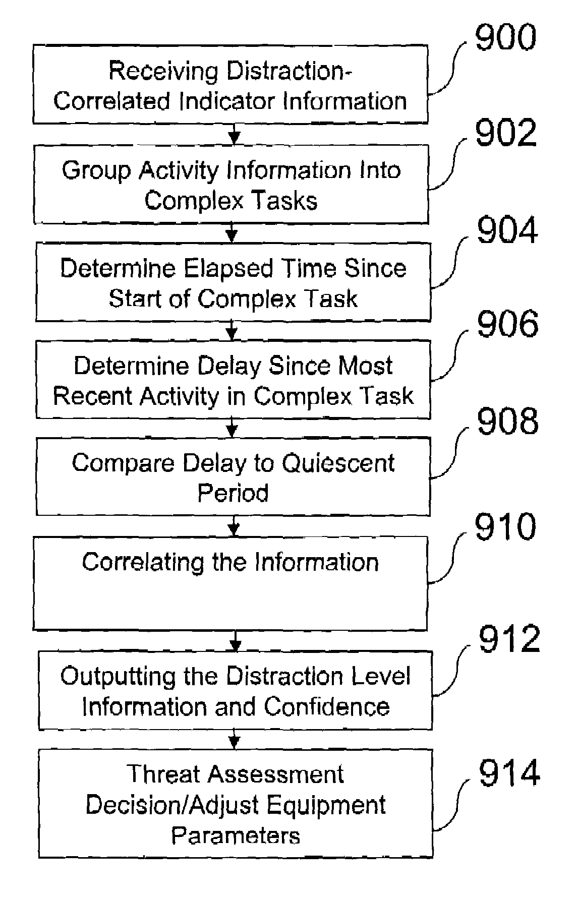
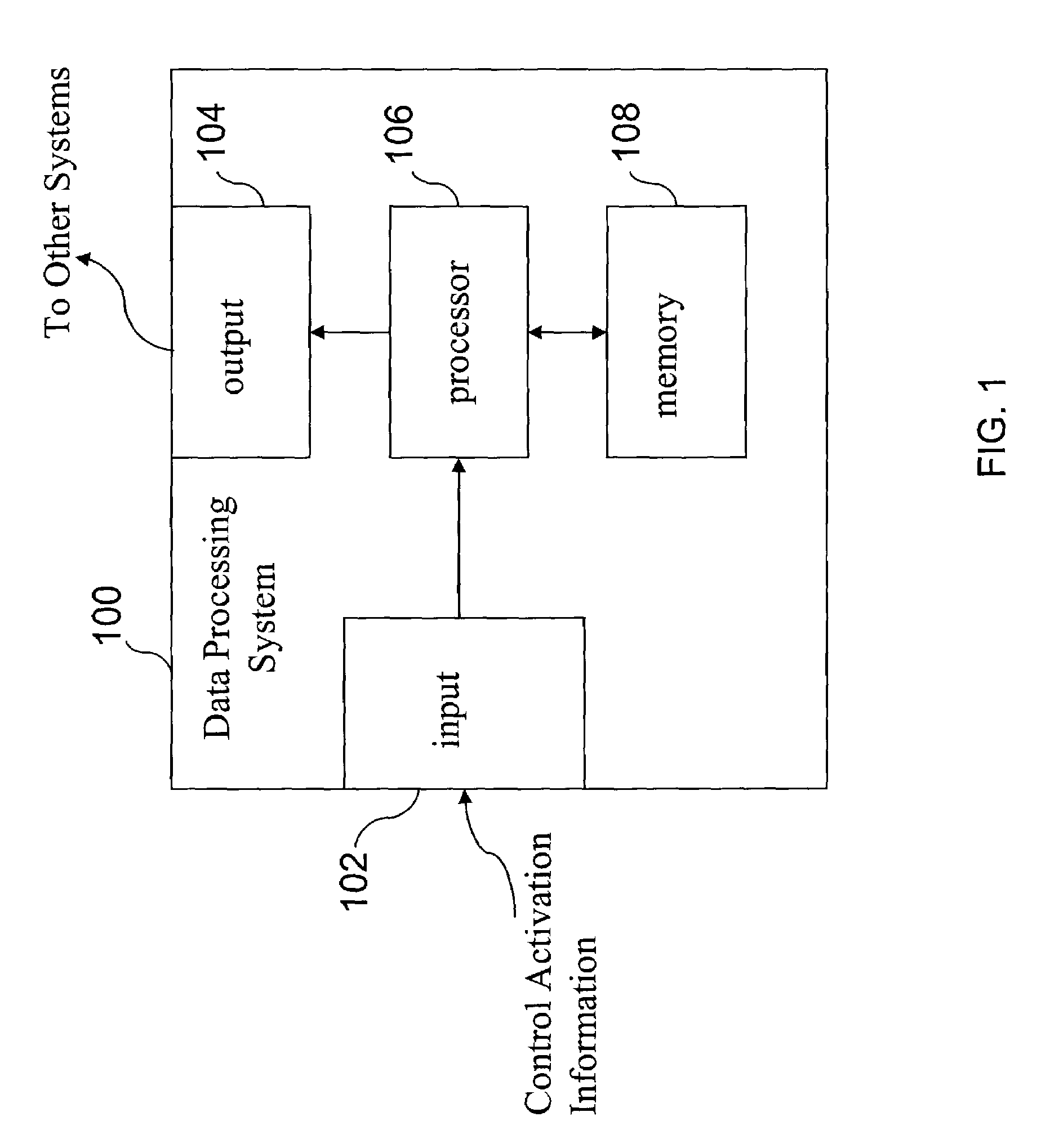
[0006]In a first aspect, the present invention provides a method, an apparatus, and a computer program product for calculating an indicator of operator distraction for an equipment operator. In a method aspect, the invention comprises a step of receiving distraction-correlated indicator information regarding the operator from devices around an operator. After the receiving step, the invention performs a step of estimating a distraction level from the information. Subsequently, a step is performed for producing an output indicative of the distraction level in order to facilitating a threat assessment decision.

Problems solved by technology

Thus, there has been significant interest recently regarding the issue of driver distraction, as well as concerns that many of the telematic features being planned for automobiles may lower their safety through increased driver distraction.
How to measure driver distraction, how to model driver cognitive workload, and how to predict distractive effects are all open, important research issues.
While the driver is glancing away to perform the secondary task, the driver's attention to the primary task of driving the vehicle is distracted, and thus secondary tasks are associated with an increased driver distraction level.

Method used


Image

  • Method and apparatus for calculating an operator distraction level
  • Method and apparatus for calculating an operator distraction level
  • Method and apparatus for calculating an operator distraction level

Examples


Embodiment Construction

[0036]The present invention relates generally to equipment operation safety and more specifically to collision warning systems based upon driver distraction levels. The following description, taken in conjunction with the referenced drawings, is presented to enable one of ordinary skill in the art to make and use the invention and to incorporate it in the context of particular applications. Various modifications, as well as a variety of uses in different applications, will be readily apparent to those skilled in the art, and the general principles defined herein, may be applied to a wide range of aspects. Thus, the present invention is not intended to be limited to the aspects presented, but is to be accorded the widest scope consistent with the principles and novel features disclosed herein. Furthermore it should be noted that unless explicitly stated otherwise, the figures included herein are illustrated diagrammatically and without any specific scale, as they are provided as qual...


PUM


Abstract

A method, apparatus, and computer program product are provided for calculating an indicator of operator distraction for an equipment operator. First, distraction-correlated indicator information from devices around an operator is received. Next, a distraction level is estimated. Subsequently, an output is produced indicative of the distraction level to facilitate a threat assessment decision. Additional operations may include grouping information into complex task types comprising sets of related activities. Next, an elapsed time is determined since the start of the first activity in a complex task. The delay since the most recent activity in the complex task is compared with a minimum task quiescent period. When the delay exceeds the minimum task quiescent period, the elapsed time and the delay are reset. Also, during the performance of a complex task, the type and the elapsed time of the complex task are correlated with other information to facilitate a threat assessment decision.

Description

PRIORITY CLAIM[0001]This application claims the benefit of priority to provisional application 60 / 354,452, titled Information “Driver Distraction Level”, filed with the United States Patent and Trademark Office on Feb. 4, 2002.TECHNICAL FIELD[0002]The present invention relates generally to automotive safety and more specifically to collision warning systems based upon driver distraction levels.BACKGROUND OF THE INVENTION[0003]According to reports by the U.S. National Highway Traffic Safety Administration, an estimated 20% of all reported automobile crashes each year involve some form of driver distraction. Thus, there has been significant interest recently regarding the issue of driver distraction, as well as concerns that many of the telematic features being planned for automobiles may lower their safety through increased driver distraction. How to measure driver distraction, how to model driver cognitive workload, and how to predict distractive effects are all open, important rese...

Claims


Application Information

Patent Timeline
Patent Type & Authority Patents(United States)
IPC IPC(8): G06F17/00B60K28/06B60R21/01B60R21/015
CPCB60K28/06B60R21/01552B60R21/01542
Inventor SHU, DAVIDSCHWARTZ, DAVID
Owner HRL LAB
Why Eureka
Try Eureka