Automated fault diagnosis method and system for engine-compressor sets

a technology of automatic fault diagnosis and engine compressor, which is applied in the direction of braking system, process and machine control, instruments, etc., can solve the problems of no automatic diagnostics, inconvenient diagnostic monitoring system for engine compressors in the gas transmission industry, etc., to improve the economic performance of engine compressor sets and fuel consumption, reduce labor maintenance time, and improve the profitability of the operating company

Inactive Publication Date: 2008-07-22
WINDROCK
View PDF14 Cites 73 Cited by
  • Summary
  • Abstract
  • Description
  • Claims
  • Application Information

AI Technical Summary

Benefits of technology

[0028]It is an object of the invention to improve the economic performance of the engine-compressor set, and fuel consumption, reduce labor maintenance time and change the “fix when brok

Problems solved by technology

Large bore, integral compressors in the gas transmission industry are not a good fit for the present diagnostic monitoring system since these large bore, integral compressor units are normally fu

Method used


Image

  • Automated fault diagnosis method and system for engine-compressor sets
  • Automated fault diagnosis method and system for engine-compressor sets
  • Automated fault diagnosis method and system for engine-compressor sets

Examples


Embodiment Construction

[0038]The present invention relates to an automated fault diagnosis method and system for a reciprocating, multiple cylinder engine driving a reciprocating, multiple cylinder compressor.

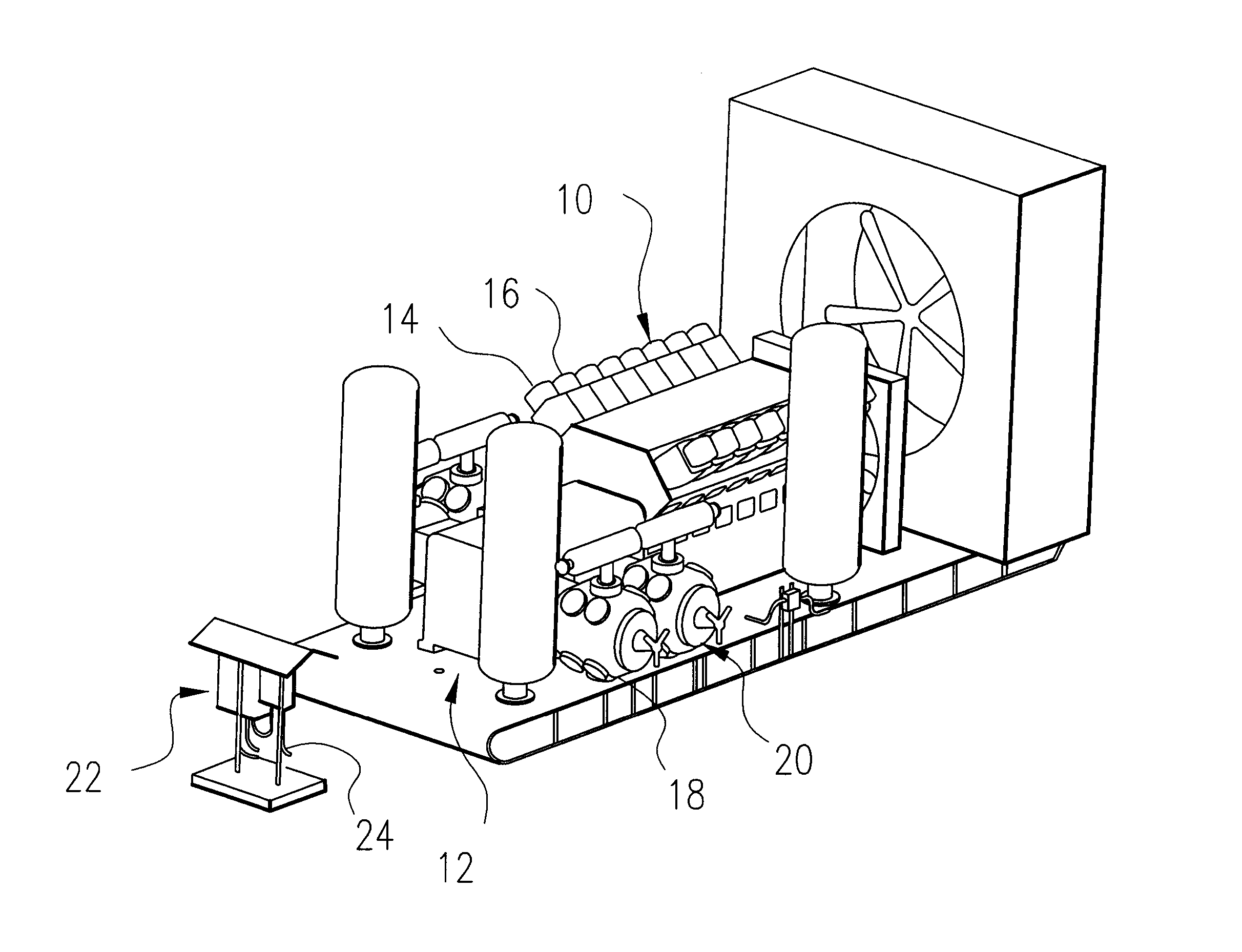
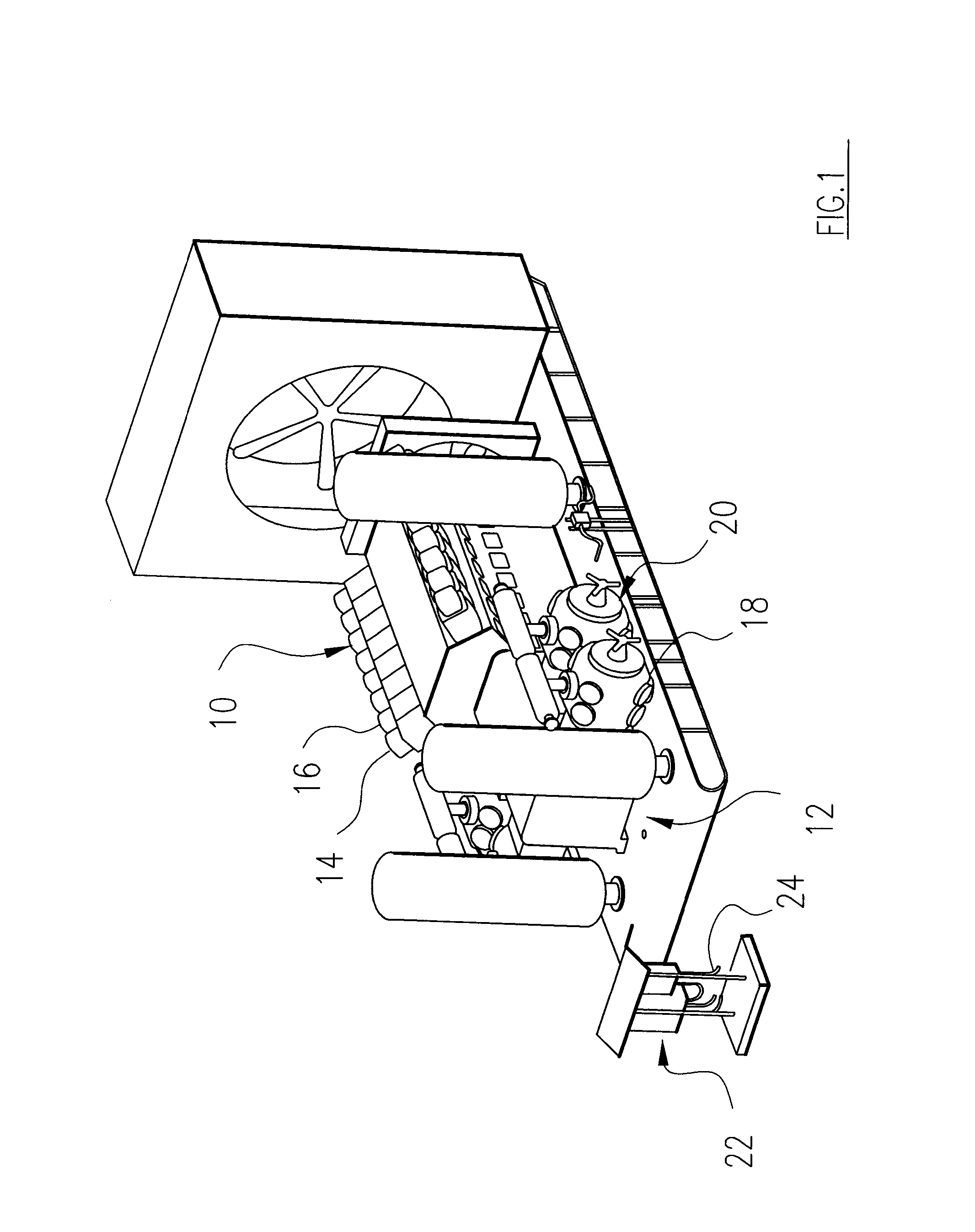
[0039]FIG. 1 diagrammatically illustrates engine 10 driving compressor 12. Engine 10 has a plurality of cylinders, two of which are identified as cylinders 14, 16. Compressor 12 has a plurality of reciprocating piston cylinders, two of which are identified as cylinders 18, 20. A control box tower 22 has power and control and sensory lines 24 which lead to various components, sensors and control elements (not shown) on the skid beneath engine 10 and compressor 12. In addition, control tower 22 is configured to send signals and data to a remotely located, central control station (not shown in FIG. 1, but shown later in connection with FIG. 6). The remotely located, central control station could be miles from the engine-compressor skid.

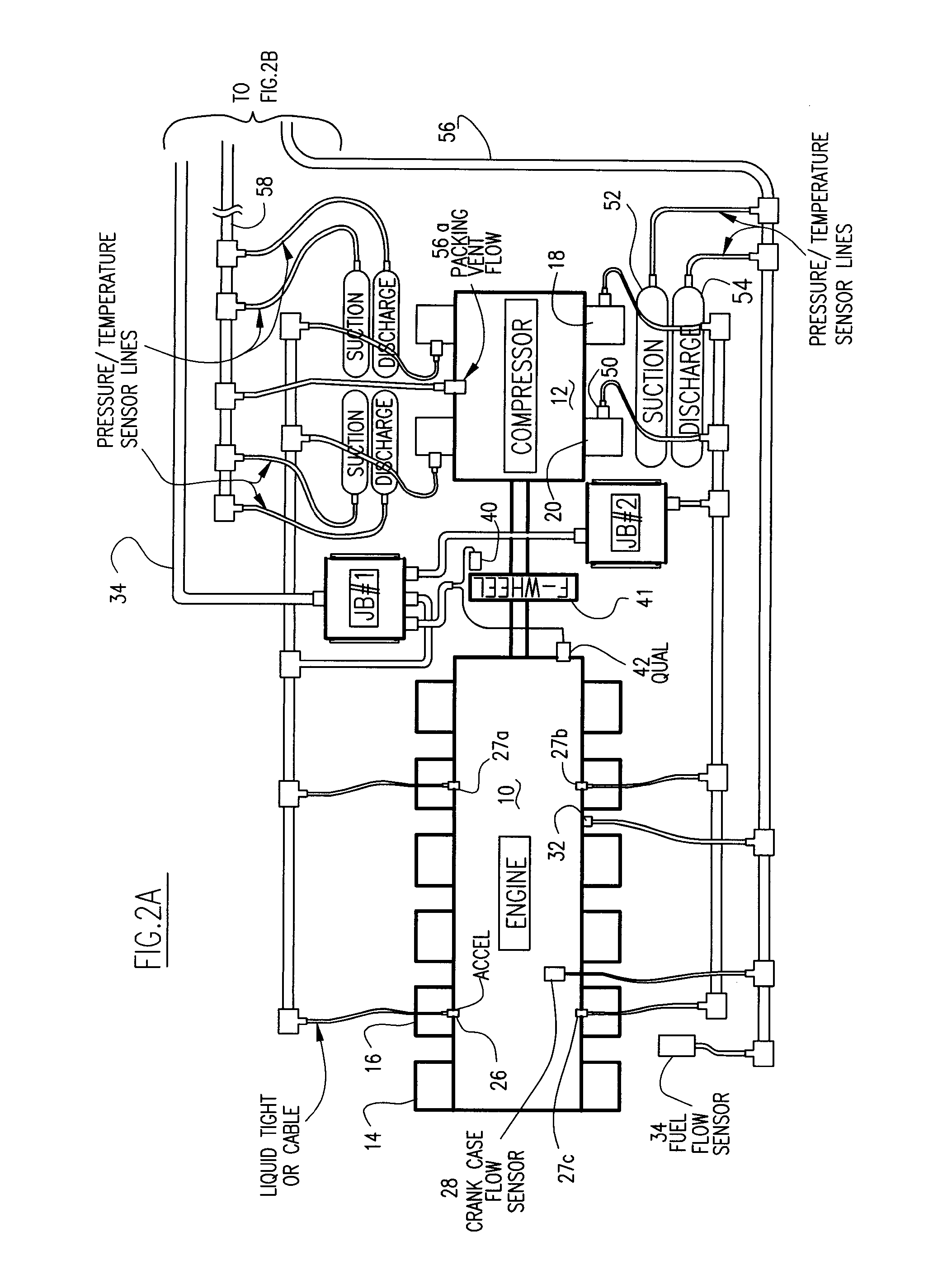
[0040]FIGS. 2A and 2B diagrammatically illustrate engine 10 driving ...


PUM


Abstract

The automated fault diagnostic system operates on engine-compressor sets with one vibration sensor per sub-group of engine cylinders and one sensor per compressor cylinder. Vibration signals linked to crankshaft phase angle windows (“VT”) mark various engine events and compressor events. In data-acquisition-learning mode, VT is stored for each engine and compressor event per operating load condition, statistical process control (SPC) theory identifies alarm threshold bands. Operator input-overrides are permitted. If no baseline data is stored, the system automatically enters the learn mode. To monitor, current VT are obtained and current load condition is matched to the earlier load set and alarms issue linking predetermined engine or compressor event to the over-under VT. Baseline data, SPC analysis, alarms and monitoring are set for crankcase flow, engine cylinder exhaust temperatures, ignition system diagnostic messages. Compressor performance alarms use suction and discharge temperatures and pressures.

Description

[0001]The present application claims priority of provisional patent application Ser. No. 60 / 721,643, filed on Sep. 29, 2005.[0002]The present invention relates to an automated fault diagnosis method and system for a reciprocating, multiple cylinder engine driving a reciprocating, multiple cylinder compressor.BACKGROUND OF THE INVENTION[0003]Large internal combustion engines are employed to drive large, multi-cylinder compressors which compressors are used in the transport of gas, such as natural gas, oil or slurry. Existing systems are adequate for basic monitoring and fault diagnosis. Current fault diagnosis of the engine-compressor sets is done by a highly trained, machinery analyst.[0004]A typical industry employing these multi-cylinder engine-compressor sets is the gas gathering industry. Large bore, integral compressors in the gas transmission industry are not a good fit for the present diagnostic monitoring system since these large bore, integral compressor units are normally ...

Claims


Application Information

Patent Timeline
IPC IPC(8): G06F7/70
CPCG01M15/05
Inventor BOUTIN, BENJAMIN J.WEBBER, JR., ROBERT J.OLIVA, FERDINAND G.KEALTY, JOHN F.FERNANDEZ, JAVIERKITCHENS, THOMAS J.
Owner WINDROCK
Why Eureka
Try Eureka