Flash memory apparatus and method for merging stored data items

a flash memory and data item technology, applied in the field of flash memory systems, can solve the problems of increasing the ratio of disabled areas to enabled areas cannot be reduced, and the conventional flash memory system cannot perform data erasing for many disabled areas inside the erasing target physical block, etc., to achieve the effect of shortening the time required for the above-described merge process, reducing the length of writing duration, and reducing the number of disabled areas

Inactive Publication Date: 2006-05-02
GK BRIDGE 1
View PDF23 Cites 64 Cited by
  • Summary
  • Abstract
  • Description
  • Claims
  • Application Information

AI Technical Summary

Benefits of technology

[0024]Furthermore, in the above-described flash memory system, the merge control section reads data on enabled pages from a predetermined physical block using the read section, and writes the data onto separate blank pages using the write section. Consequently, data on enabled pages inside the predetermined physical block can be copied into other physical blocks. In particular, when the data copying is finished on all the enabled pages inside the predetermined physical block, the erase section collectively erases data in the physical block. Thereafter, the copying of data on the enabled pages and the subsequent erasure of data in the physical block are referred to as a merge process. The above-described flash memory system can erase data through the merge process on the disabled pages in the physical block that includes enabled pages, in contrast to conventional systems. Accordingly, the above-described flash memory system can reduce the rate of the disabled pages to the enabled pages. As a result, the amount of data that can be stored when overwriting is repeated is larger than that in the conventional systems.
[0044]In the above-described method for merging, the step of selecting the source physical block may comprise the substep of consulting a list of the addresses of the physical blocks and the numbers of the disabled pages that belong to the physical blocks. Consequently, the source physical block can be selected easily and quickly in decreasing order of the number of the disabled pages that the physical blocks include. As a result, the time required to the above-described merge process can shorten since the number of the enabled pages whose data should be copied is minimized.

Problems solved by technology

Furthermore, a portable information processing device must operate for a long period of time using only an internal power supply such as a battery.
The result is an increase in the number of the disabled areas.
Therefore, the conventional flash memory system cannot perform data erasing for many disabled areas inside the erasing target physical block when the physical block includes even one enabled area.
Accordingly, the ratio of the disabled areas to the enabled areas cannot be reduced.
As a result, in the conventional flash memory system, the repetition of the overwriting operation seriously reduces the amount of data that can be stored in the flash memory compared with the storage capacity of the flash memory.

Method used


Image

  • Flash memory apparatus and method for merging stored data items
  • Flash memory apparatus and method for merging stored data items
  • Flash memory apparatus and method for merging stored data items

Examples


embodiment 1

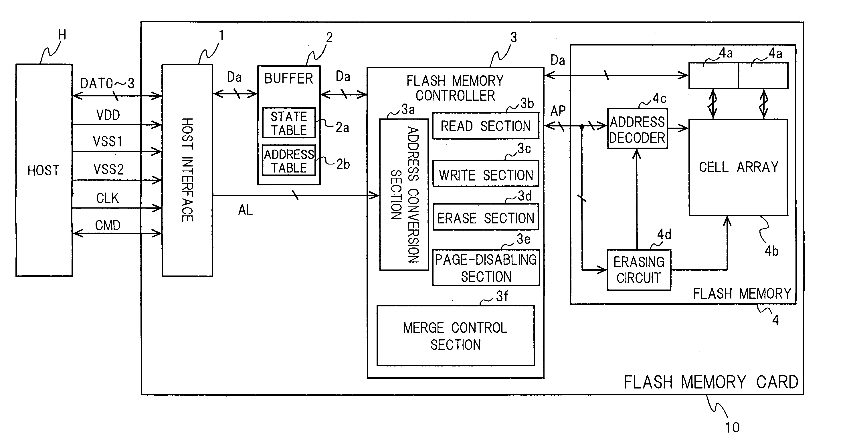
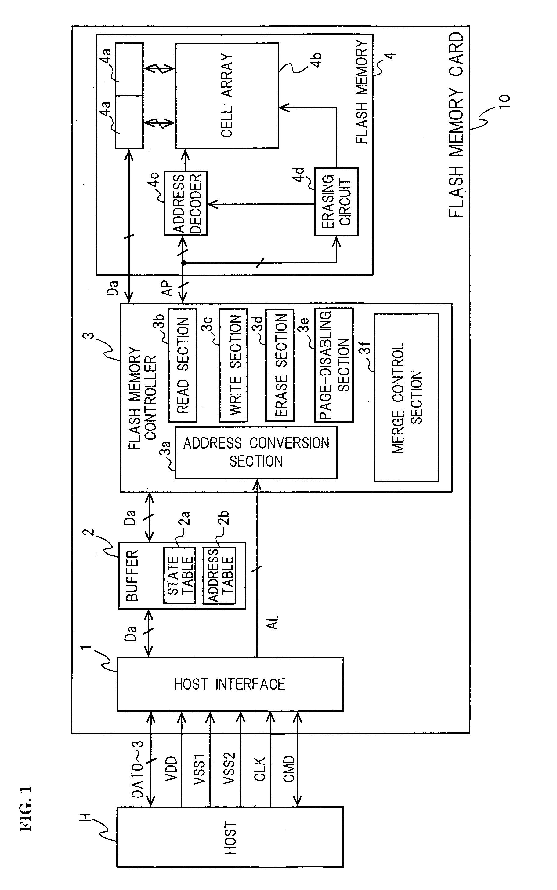
[0058]FIG. 1 is a block diagram showing data exchanges between a flash memory card 10 according to Embodiment 1 of the present invention and a host H. The flash memory card 10 is connected with the host H through the following five types of lines. The lines are composed of nine lines in total; four data lines DAT0–3, a clock line CLK, a power line VDD, two ground lines VSS1 and VSS2, and a command line CMD.

[0059]A host interface 1 is the circuit for performing communications directly with the host H through the above-mentioned nine lines. The host interface 1 receives commands from the host H through the command line CMD and decodes the commands. After that, the host interface performs, for example, the following operations in response to the commands. When a command from the host H is a read command, the host interface 1 decodes the command into the logical address AL of the read target and sends the address to a flash memory controller 3. When a command from the host H is a write ...

embodiment 2

[0125]FIG. 8 is a block diagram showing data exchanges between a flash memory card 10A according to Embodiment 2 of the present invention and a host H. The flash memory card 10A according to Embodiment 2 comprises two flash memories in contrast to the counterpart 10 of Embodiment 1 (FIG. 1). In FIG. 8, components similar to those of Embodiment 1 are marked with the same reference symbols as those of Embodiment 1. Furthermore, the description of Embodiment 1 is cited regarding those similar components.

[0126]A flash memory controller 3A and two flash memories 4A and 4B according to Embodiment 2 are really similar in internal structure to their respective counterparts 3 and 4 of Embodiment 1, and therefore FIG. 1 is cited regarding them.

[0127]The duration of data transfer between the flash memory controller 3A and the flash memory 4A or 4B inside the page buffers 4a is on the order of several tens of nsec. On the other hand, the duration of writing data from the page buffer 4a into the...

embodiment 3

[0133]FIG. 9 is a block diagram showing data exchanges between a flash memory card 10B according to Embodiment 3 of the present invention and a host H. The flash memory card 10B according to Embodiment 3 comprises two flash memories in a manner similar to the counterpart 10A of Embodiment 2 (FIG. 8). In FIG. 9, components similar to those of Embodiment 1 are marked with the same reference symbols as those of Embodiment 1. Furthermore, the description of Embodiment 1 is cited regarding those similar components.

[0134]The two flash memories 4A and 4B according to Embodiment 3 are really similar in internal structure to their counterpart 4 of Embodiment 1, and therefore FIG. 1 is cited regarding them.

[0135]A flash memory controller 3B according to Embodiment 3 includes two internal structures, each of which is similar to that of its counterpart 3 according to Embodiment 1. Of the internal structures similar to that of the flash memory controller 3 according to Embodiment 1, one is conne...


PUM


Abstract

A flash memory system is disclosed. The flash memory system includes a flash memory comprising more than one physical block and more than one page, where each page can be in an enabled state, a blank state or a disabled state. In use, a merge control section reads data on an enabled page from a predetermined physical block using a read section, and writes the data onto a blank page using a write section, thereby copying the data on the enabled page onto the blank page. A merge control section then disables the enabled page using a page-disabling section. When the copying of the data from all the enabled pages in the predetermined physical block is finished, the merge control section collectively erases all the data in the physical block using an erase section.

Description

CROSS-REFERENCE TO RELATED APPLICATION[0001]This application is a Section 371 of International Application No. PCT / JP02 / 07456, filed Jul. 23, 2002, the disclosure of which is incorporated herein by reference.TECHNICAL FIELD[0002]The present invention relates to a flash memory system comprising flash memories and, in particular, a method for merging data items stored in each of the flash memories.BACKGROUND ART[0003]A portable information processing device, such as a notebook computer, personal digital assistant (PDA), or digital camera, records large quantities of digital data, such as image data, in an internal recording medium. A recording medium that is compact, lightweight and has a large-recording-capacity is desirable. In particular, a portable information processing device, such as a digital video camera (DVC) or an audio player, must record or reproduce large quantities of data from a recording medium in real time. Accordingly, a recording medium that can manipulate large qu...

Claims


Application Information

Patent Timeline
Patent Type & Authority Patents(United States)
IPC IPC(8): G06F12/12G11C16/02G06F12/00G06F12/02G11C16/10
CPCG06F12/0246Y10S707/99956Y10S707/99953G11C16/102G11C16/02
Inventor IWATA, KAZUYAKOGITA, SHIGEKAZUTAKEUCHI, AKIO
Owner GK BRIDGE 1
Why Eureka
Try Eureka