
Tip-up vehicle seat

Active Publication Date: 2006-05-09
TS TECH CO LTD +1
View PDF4 Cites 28 Cited by
  • Summary
  • Abstract
  • Description
  • Claims
  • Application Information

AI Technical Summary

Benefits of technology

[0004]It is an object of the present invention to provide a tip-up vehicle seat which has an improved operability and where no wrong operation is caused. In order to achieve this object, a lock mechanism for holding a seat bottom at the retracted position is arranged to be released by a movement from a retracted position to a support position of a leg member.
[0005]Furthermore, it is another object of the present invention to provide improved attaching means for attaching a leg member and connecting means which transmit the movement of the leg member to the lock mechanism.

Problems solved by technology

If anyone sits on the seat bottom at the available position while the leg member is not positioned at the support position, the seat bottom may be deformed by large load.
Thus, in using, a conventional seat is delicate and troublesome.

Method used


Image

  • Tip-up vehicle seat
  • Tip-up vehicle seat
  • Tip-up vehicle seat

Examples


Embodiment Construction

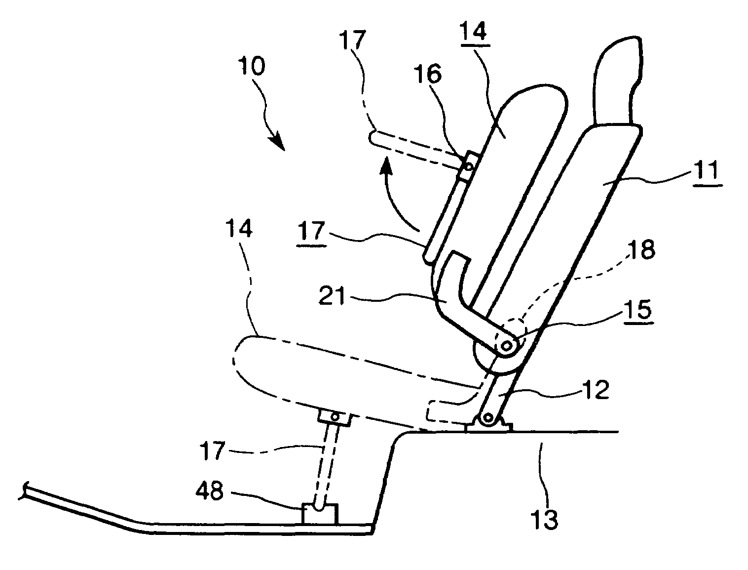
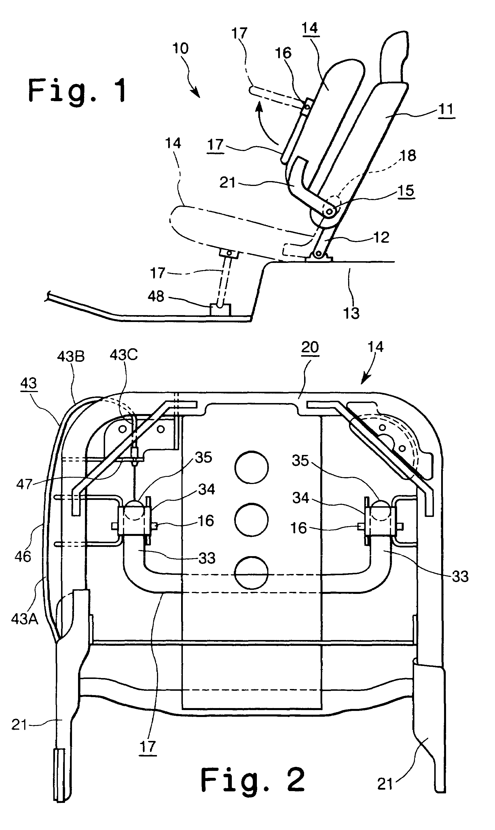
[0011]One embodiment of the present invention will be described by referring to drawings. A tip-up vehicle seat 10 according to the present invention includes a seat back 11 attached to a vehicle body 13 through a stay 12 and a retractable seat bottom 14 rotatably attached to the seat back 12 by support means 15. The seat bottom 14 is displaceable between a retracted position where it becomes substantially in parallel with the seat back 11 and an available or horizontal position where it becomes approximately at right angles to the seat back 11.

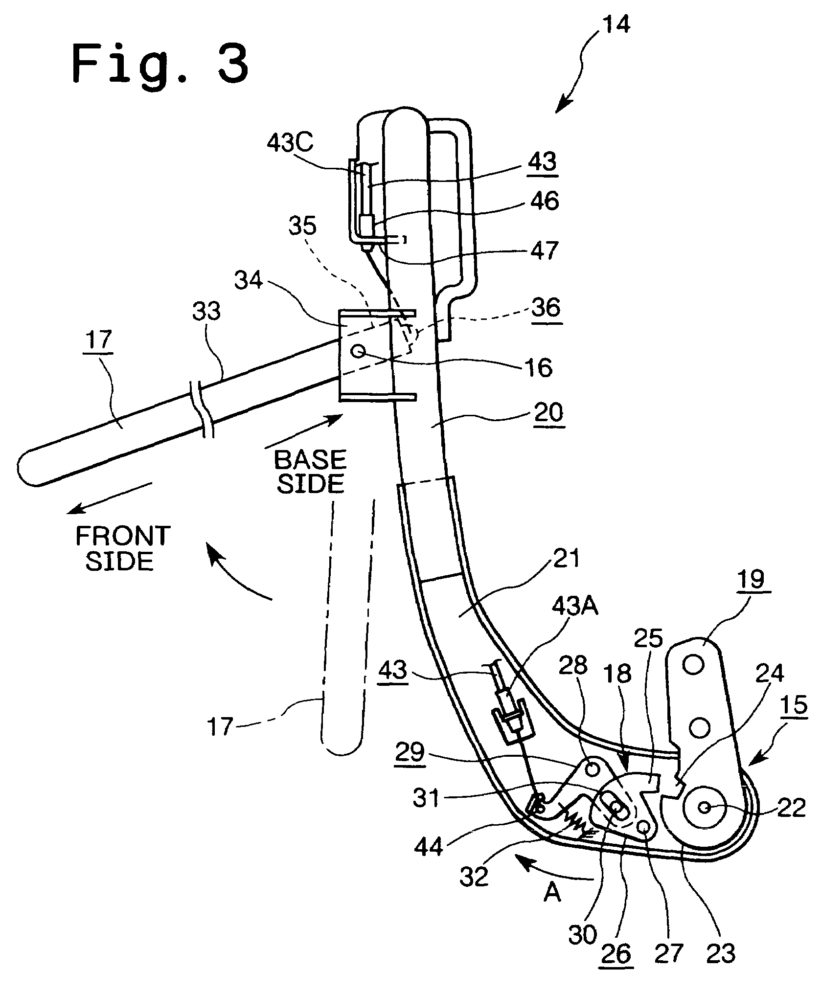
[0012]At the under surface of the seat bottom 14, a retractable leg member 17 is rotatably attached by a mounting shaft 16. The leg member 17 is displaceable between a retracted position where it becomes substantially in parallel with the seat bottom 14 and a support position where it becomes approximately at a right angle to the seat bottom 14.

[0013]The support means 15 has a lock mechanism 18 for holding the seat bottom 14 at the retracted ...


PUM


Abstract

A tip-up vehicle seat comprises a seat back (11) attached to a vehicle body, a seat bottom (14) displaceable between a retracted position and a available position, a leg member (17) displaceable between a retracted position and a support position, a lock mechanism (18) arranged to hold the seat bottom at the retracted position. The lock mechanism (18) is connected to the leg member (17) through a wire cable (43) so that the lock mechanism (18) is unlocked by rotational movement of the leg member (17) from the retracted position toward the support position to release the restriction to the seat bottom (14).

Description

TECHNICAL FIELD OF THE INVENTION[0001]The present invention relates to a tip-up vehicle seat, and more particularly, relates to a lock mechanism of a tip-up seat.BACKGROUND ART OF THE INVENTION[0002]Japanese Utility Model Application Laid-Open No. 4-14536 discloses a tip-up vehicle seat which includes a seat back attached to a vehicle body, a seat bottom rotatably attached to the seat back, and a leg member rotatably attached to the seat bottom. The seat bottom is displaceable between a retracted position where it becomes substantially in parallel with the seat back and an available or horizontal position where it becomes approximately at right angles with the seat back. The leg member is displaceable between a retracted position where it becomes substantially in parallel with the seat bottom and a support position where it becomes approximately at right angles with the seat bottom. The seat bottom is held at the retracted position with a lock mechanism.[0003]For using this vehicle ...

Claims


Application Information

Patent Timeline
IPC IPC(8): A47C1/02B60N2/30B60N2/36
CPCB60N2/3009B60N2/3013B60N2/366B60N2/3072B60N2/3047
Inventor YAMADA, TAKUROUTAKAKURA, MASAYUKIITO, TAKAHIROWAKU, SEIJI
Owner TS TECH CO LTD
Learn More