Multiple views for a measurement system diagram

a measurement system and diagram technology, applied in the field of measurement systems, can solve the problems of difficult to efficiently design and implement a measurement system, scientists and engineers are not highly trained in the art of computer-based measurement system design, and the difficulty of designing a measurement system to meet the objectiv

Active Publication Date: 2006-05-09
NATIONAL INSTRUMENTS
View PDF28 Cites 20 Cited by
  • Summary
  • Abstract
  • Description
  • Claims
  • Application Information

AI Technical Summary

Benefits of technology

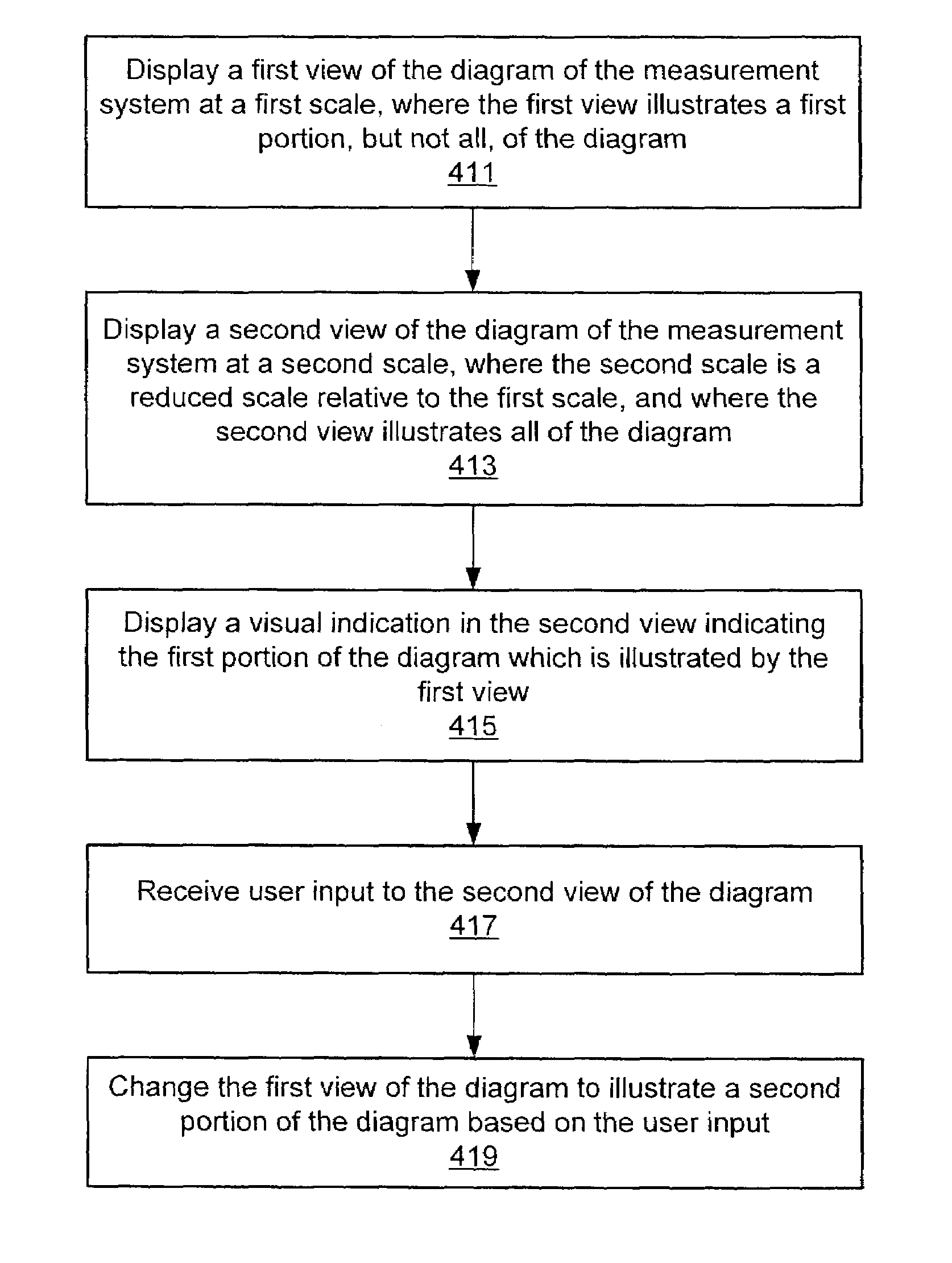
[0011]One embodiment of the present invention comprises a method for displaying multiple views of a diagram of a measurement system. In one embodiment, the method may be used in conjunction with a software application operable to assist a user in designing and/or implementing the measurement system. One embodiment of such a software application is referred to herein as the Measurement System Designer (MSD) environment. Th

Problems solved by technology

However, due to the wide variety of possible testing and control situations and environments, and also the wide array of instruments or devices available, designing a measurement system to meet the objective can be a difficult task.
Often, scientists and engineers are not highly trained in the art of designing a computer based measurement system.
As a result, in many cases it is difficult to efficiently design and implement a measurement system, and the proc

Method used


Image

  • Multiple views for a measurement system diagram
  • Multiple views for a measurement system diagram
  • Multiple views for a measurement system diagram

Examples


Embodiment Construction

Incorporation by Reference

[0043]The following references are hereby incorporated by reference in their entirety as though fully and completely set forth herein:

[0044]U.S. Pat. No. 4,914,568 titled “Graphical System for Modeling a Process and Associated Method,” issued on Apr. 3, 1990.

[0045]U.S. Pat. No. 5,481,741 titled “Method and Apparatus for Providing Attribute Nodes in a Graphical Data Flow Environment”.

[0046]U.S. Pat. No. 6,173,438 titled “Embedded Graphical Programming System” filed Aug. 18, 1997.

[0047]U.S. Pat. No. 6,219,628 titled “System and Method for Configuring an Instrument to Perform Measurement Functions Utilizing Conversion of Graphical Programs into Hardware Implementations,” filed Aug. 18, 1997.

[0048]U.S. patent application Ser. No. 09 / 617,600 titled “Graphical Programming System with Distributed Block Diagram Execution and Front Panel Display,” filed Jun. 13, 2000.

[0049]U.S. patent application Ser. No. 09 / 518,492 titled “System and Method for Programmatically Cre...


PUM


Abstract

A system and method for displaying multiple views of a diagram of a measurement system. A first view of the diagram of the measurement system may be displayed at a first scale. The first view may illustrate a first portion, but not all, of the diagram. A second view of the diagram of the measurement system may be displayed at a second scale, where the second scale is a reduced scale relative to the first scale. The second view may illustrate all of the diagram, e.g., may provide an overview of the entire measurement system. The second view may be displayed on a substantially smaller area of the display than the first view of the diagram. For example, in the first view of the diagram, components of the measurement system may be displayed at a scale large enough to enable the user to interact with the components. On the other hand, the second view of the diagram may not be intended for editing the diagram, and components of the measurement system may be displayed at a small scale in the second view. A visual indication may be displayed within the second view to indicate the first portion of the diagram which is illustrated by the first view. In one embodiment, the second view of the diagram may enable the user to navigate through the diagram, i.e., to change the portion of the diagram illustrated by the first view.

Description

PRIORITY INFORMATION[0001]This application claims the benefit of priority of U.S. Provisional Application No. 60 / 403,135, titled “Icon to Represent Unspecified Component in a Measurement System,” whose inventors were Kamran Shah, Jeffrey L. Kodosky and David W Fuller III, filed on Aug. 13, 2002.[0002]This application also claims the benefit of priority of U.S. Provisional Application No. 60 / 403,822 titled “Icon to Represent Unspecified Component in a Measurement System,” whose inventors were Kamran Shah, Jeffrey L. Kodosky, David W Fuller, Brian Sierer and Jeff Correll, filed on Aug. 15, 2002.FIELD OF THE INVENTION[0003]The present invention relates to the field of measurement systems, and more particularly to a software application that guides a user through a process of creating a measurement system.DESCRIPTION OF THE RELATED ART[0004]Scientists and engineers often use test, measurement or automation systems to perform a variety of functions, including measurement of a physical ph...

Claims


Application Information

Patent Timeline
IPC IPC(8): G09G5/00G06T11/20
CPCG06T11/206
Inventor FULLER, DAVID W
Owner NATIONAL INSTRUMENTS
Why Eureka
Try Eureka