Airflow meter

a technology of airflow meter and airflow speed, which is applied in the direction of volume/mass flow measurement, measurement devices, instruments, etc., can solve the problems of reducing airflow speed and spoiling measuring accuracy, and achieve the effect of restricting airflow separation, reducing pressure loss, and reducing turbulen

Active Publication Date: 2006-05-16
DENSO CORP
View PDF4 Cites 24 Cited by
  • Summary
  • Abstract
  • Description
  • Claims
  • Application Information

AI Technical Summary

Benefits of technology

[0009]The present invention is achieved in view of the above-described issues and has an object to provide an airflow meter capable of decreasing a pressure loss by disposing a restriction portion in the bypass passage and restricting a separation in an airflow and / or a turbulence of an air in a vicinity of a sensing portion.

Problems solved by technology

Thus, in the small airflow condition, an airflow speed is decreased and fluctuated to cause an issue of spoiling a measuring accuracy.

Method used


Image

  • Airflow meter
  • Airflow meter
  • Airflow meter

Examples


first embodiment

(First Embodiment)

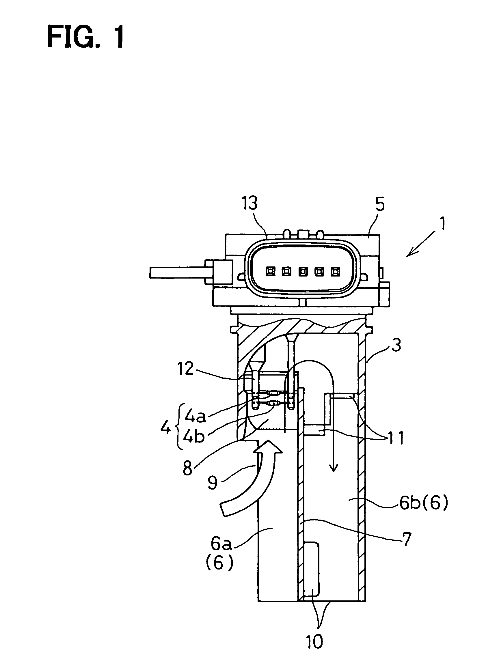
[0029]An airflow meter 1 described in a first embodiment is used as an airflow meter 1 for detecting the intake air amount of an internal combustion engine. As shown in FIG. 1, the airflow meter 1, and disposed in an intake duct 2, which forms an air passage of the present invention, as shown in FIG. 3. The airflow meter 1 is composed of a mensurative body 3, a sensing portion 4, a circuit module 5 and so on.

[0030]The mensurative body 3 is inserted into the intake duct 2 through a mounting hole 2a formed on the intake duct 2 to be exposed in an air flowing in the intake duct 2.

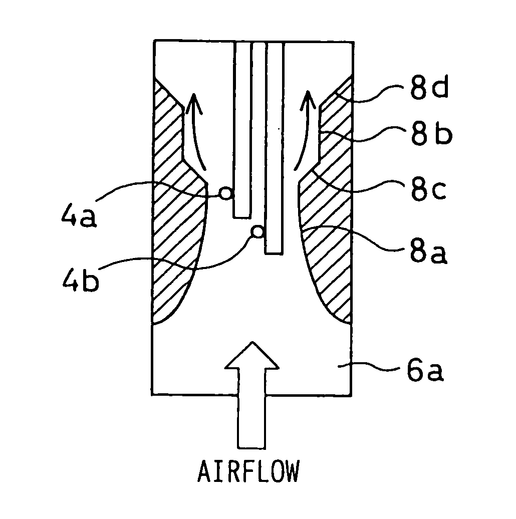
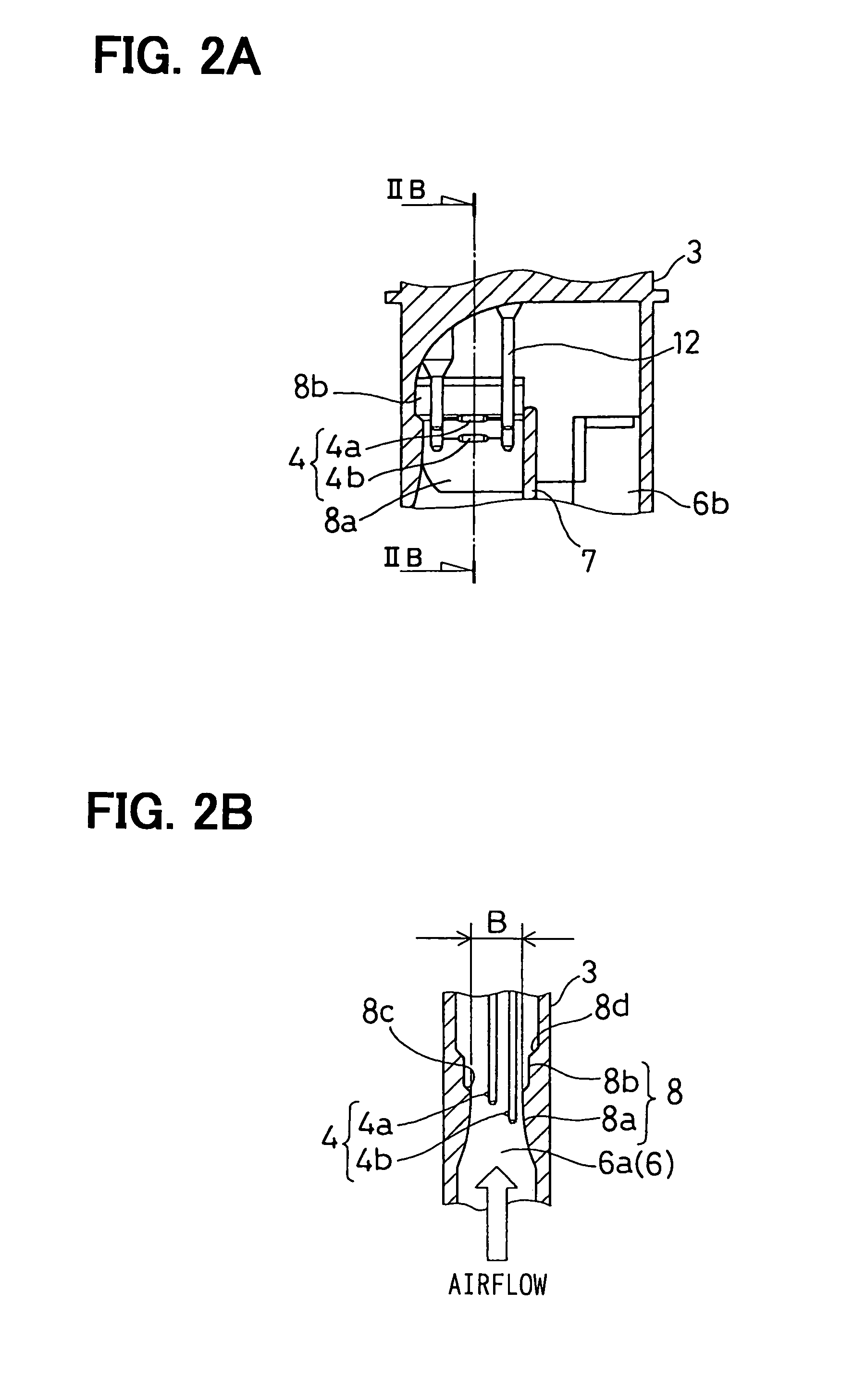
[0031]The mensurative body 3 is provided in a planiform shape of which a dimension in a thickness direction is smaller than that in a width direction shown in FIG. 1, and disposed so that the width direction is along an airflow direction in the intake duct 2 (refer to FIG. 3). In the following description, the air flowing in the intake duct 2 is referred to as a main flowing air and the airfl...


PUM


Abstract

An airflow meter has a bypass passage disposed in an air passage and a sensing portion disposed in the bypass passage to detect an airflow amount. The bypass passage is provided with a restriction portion to gradually decrease a passage width of the bypass passage in an airflow direction in the bypass passage. The restriction portion includes a first restriction portion and the second restriction portion disposed at an immediately downstream side of a narrowest portion of the first restriction portion. The first restriction portion gradually decreases the passage width in the airflow direction. The second restriction portion increases the passage width than the passage width at the narrowest portion in a stepped manner. The sensing portion is located in a bound in which the restriction portion is disposed.

Description

CROSS REFERENCE TO RELATED APPLICATION[0001]This application is based on Japanese Patent Application No. 2004-134210 filed on Apr. 28, 2004, the content of which is incorporated herein by reference.FIELD OF THE INVENTION[0002]The present invention relates to an airflow meter that has a bypass passage in an air passage and a sensing portion located in the bypass passage to detect an airflow amount.BACKGROUND OF THE INVENTION[0003]As a conventional art, JP-2002-357465-A, for example, discloses an airflow meter.[0004]The airflow meter is for measuring an intake air amount of an internal combustion engine for example. As shown in FIG. 8, the airflow meter has a bypass passage 100 to introduce a part of the intake air and a sensing portion 110 disposed in the bypass passage 100 to measure an airflow amount.[0005]The bypass passage 100 has a restriction portion 120 having a three-dimensional structure to gradually decrease a cross-sectional area of the passage in an airflow direction. By ...

Claims


Application Information

Patent Timeline
Patent Type & Authority Patents(United States)
IPC IPC(8): G01F1/68G01F1/684G01F1/688G01F5/00
CPCG01F5/00G01F1/6842
Inventor GOKA, YASUSHIMATSUURA, HIDEKIKITAHARA, NOBORU
Owner DENSO CORP
Why Eureka
Try Eureka