Grip adjusting insert for a hole in a bowling ball

a technology for adjusting inserts and bowling balls, which is applied to bowling balls, sports equipment, solid balls, etc., can solve problems such as unsuitable purposes, and achieve the effect of simple and inexpensive manufacture and simple us

Inactive Publication Date: 2006-05-16
BREWSTER FREDERICK A
View PDF13 Cites 18 Cited by
  • Summary
  • Abstract
  • Description
  • Claims
  • Application Information

AI Technical Summary

Benefits of technology

[0014]ANOTHER OBJECT of the present invention is to provide a grip adjusting insert for a hole in a bowling ball that is simple and inexpensive to manufacture.
[0015]STILL ANOTHER OBJECT of the present invention is to provide a grip adjusting insert for a hole in a bowling ball that is simple to use.

Problems solved by technology

Furthermore, even though these innovations may be suitable for the specific individual purposes to which they address, however, they would not be suitable for the purposes of the present invention as heretofore described.

Method used


Image

  • Grip adjusting insert for a hole in a bowling ball
  • Grip adjusting insert for a hole in a bowling ball

Examples


Embodiment Construction

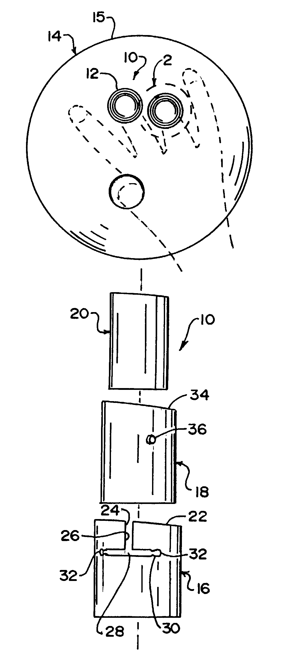
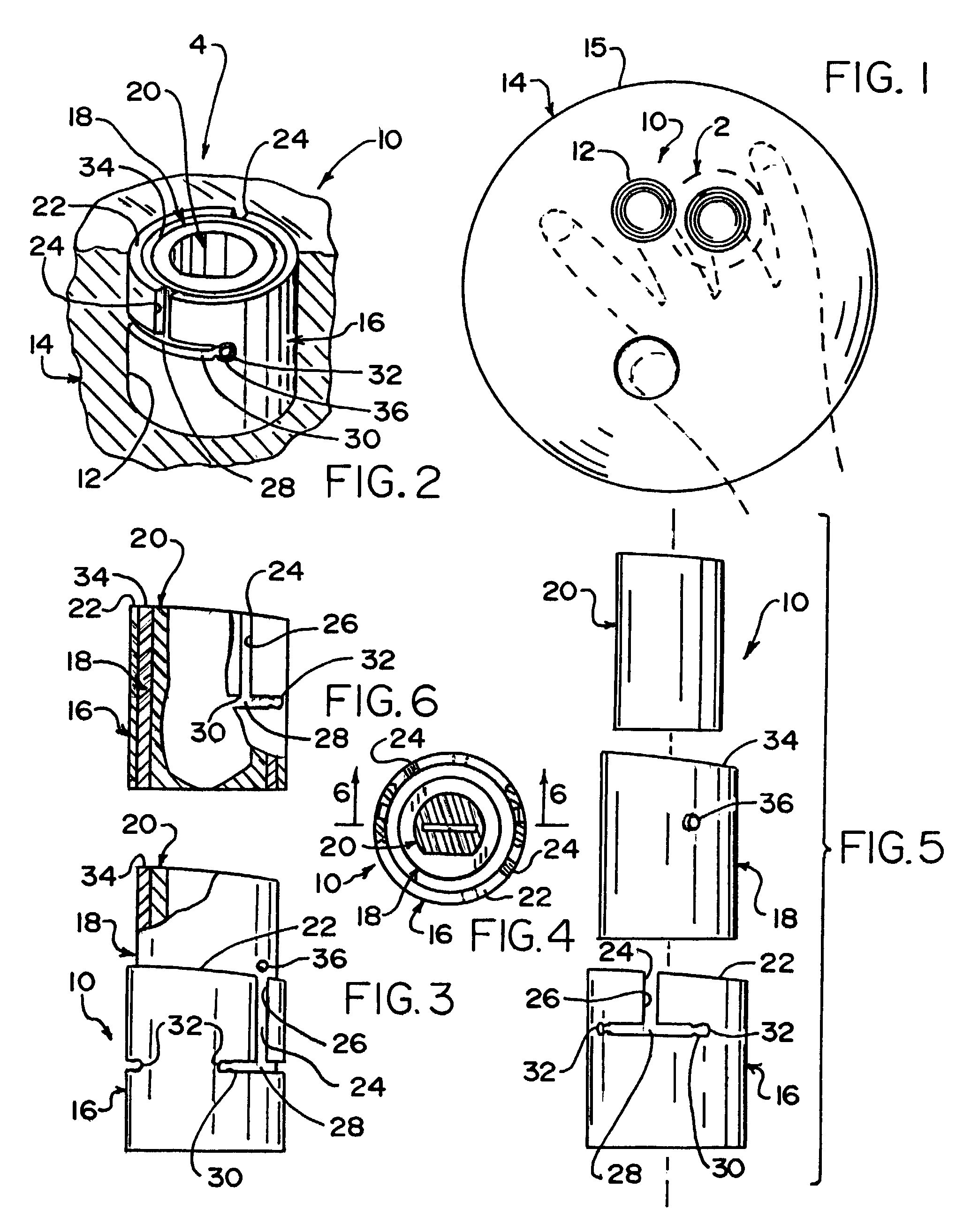
[0040]Referring now to the figures, in which like numerals indicate like parts, and particularly to FIG. 1, the grip adjusting insert of the present invention is shown generally at 10 for a hole 12 in a bowling ball 14, wherein the bowling ball 14 has an outer contour 15.

[0041]The configuration of the grip adjusting insert 10 can best be seen in FIGS. 2–6, and as such, will be discussed with reference thereto.

[0042]The grip adjusting insert 10 comprises an outer sleeve 16 and an inner sleeve 18. The outer sleeve 16 is for inserting in the hole 12 in the bowling ball 14 and the inner sleeve 18 is movably mounted in the sleeve 16.

[0043]The grip adjusting insert 10 further comprises a finger-engaging member 20. The finger-engaging member 20 is affixed in the inner sleeve 18 and is for conforming to a finger of a user.

[0044]The outer sleeve 16 has an uppermost surface 22. The uppermost surface 22 of the outer sleeve 16 is arched for matching the outer contour 15 of the bowling ball 14.

[...


PUM


Abstract

A grip adjusting insert for a hole in a bowling ball. An outer sleeve is inserted in the hole in the bowling ball, an inner sleeve is movably mounted in the sleeve, and a finger-engaging member is affixed in the inner sleeve and conforms to a finger of a user. The outer sleeve has a pair of throughslots that are inverted T-shaped. The inner sleeve has a pair of pins that ride axially downwardly in the pair of throughslots in the outer sleeve, respectively, when the inner sleeve is inserted into the sleeve, and at which time, the inner sleeve is rotated relative to the outer sleeve so as to cause the pair of pins to move laterally in the pair of throughslots in the outer sleeve, respectively. The finger-engaging member is rubber poured into the inner sleeve, with a finger therein so as to conform thereto.

Description

BACKGROUND OF THE INVENTION[0001]1. Field of the Invention[0002]The present invention relates to a grip adjusting insert. More particularly, the present invention relates to a grip adjusting insert for a hole in a bowling ball.[0003]2. Description of the Prior Art[0004]Numerous innovations for bowling ball inserts have been provided in the prior art that will be described. Even though these innovations may be suitable for the specific individual purposes to which they address, however, they differ from the present invention.[0005]A FIRST EXAMPLE, U.S. Pat. No. 3,416,796 to Ginder teaches a cylindrical longitudinally-slotted finger-receiving insert that is axially movable within a cylindrical sleeve secured in a bowling ball. When moved axially by a securing bolt passing through a closure member at one end of the insert and into the ball, tapered walls of the insert and sleeve coact to charge the inner diameter of the insert without changing the angular relationship between the inser...

Claims


Application Information

Patent Timeline
Patent Type & Authority Patents(United States)
IPC IPC(8): A63B37/00
CPCA63B37/0002
Inventor BREWSTER, FREDERICK A.
Owner BREWSTER FREDERICK A
Why Eureka
Try Eureka