

Golf tee marking template
a golf tee and template technology, applied in the field of golf tee marking templates, can solve the problems of tee breaking, slowing down play, bit awkward or cumbersome, etc., and achieve the effect of consistent tee heigh
- Summary
- Abstract
- Description
- Claims
- Application Information
AI Technical Summary
Benefits of technology
Problems solved by technology
Method used
Image

Examples
Embodiment Construction
[0014]The disclosed inventions relate generally to a marking template for a golf tee that allows for marking a golf tee at selected distances from one end of the golf tee.
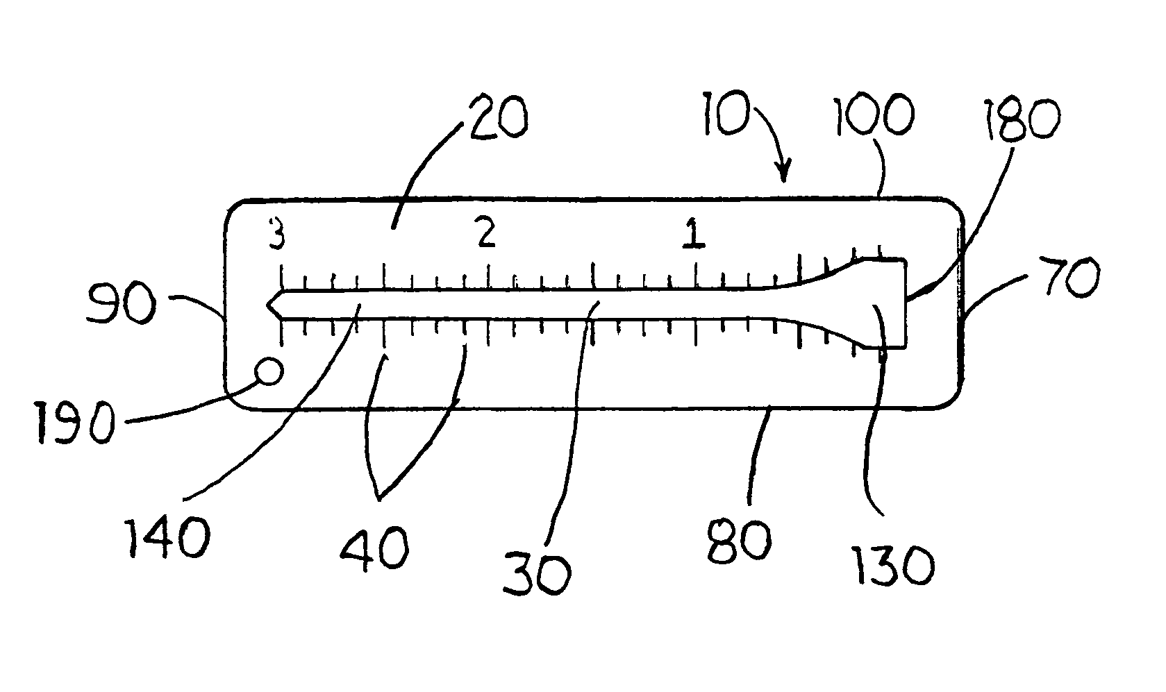
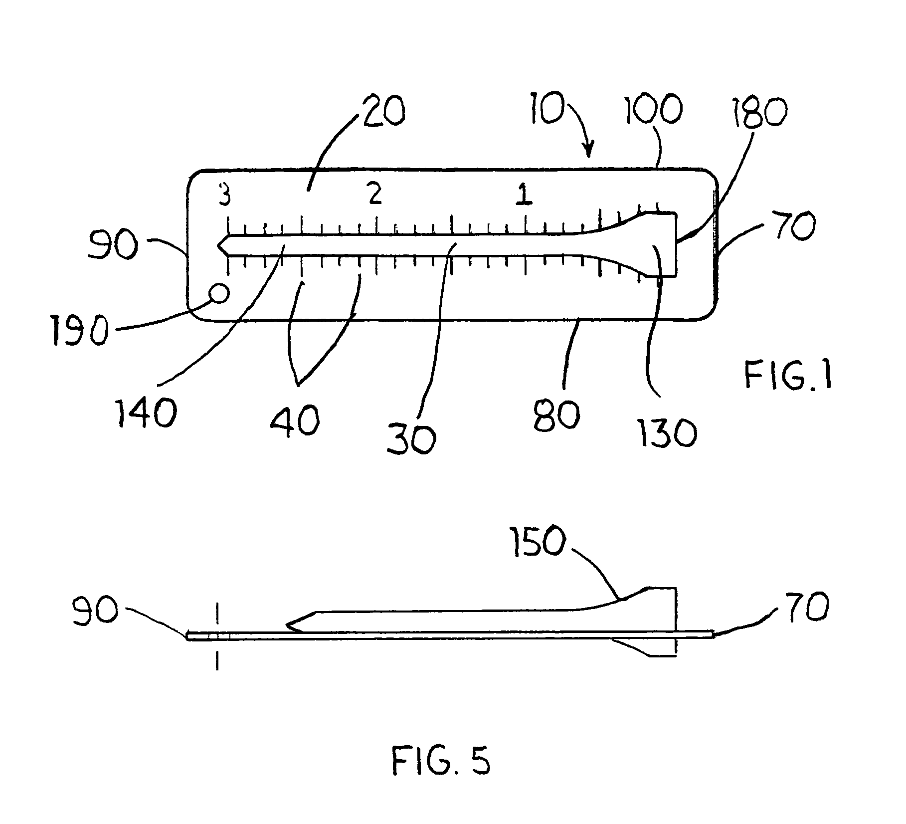
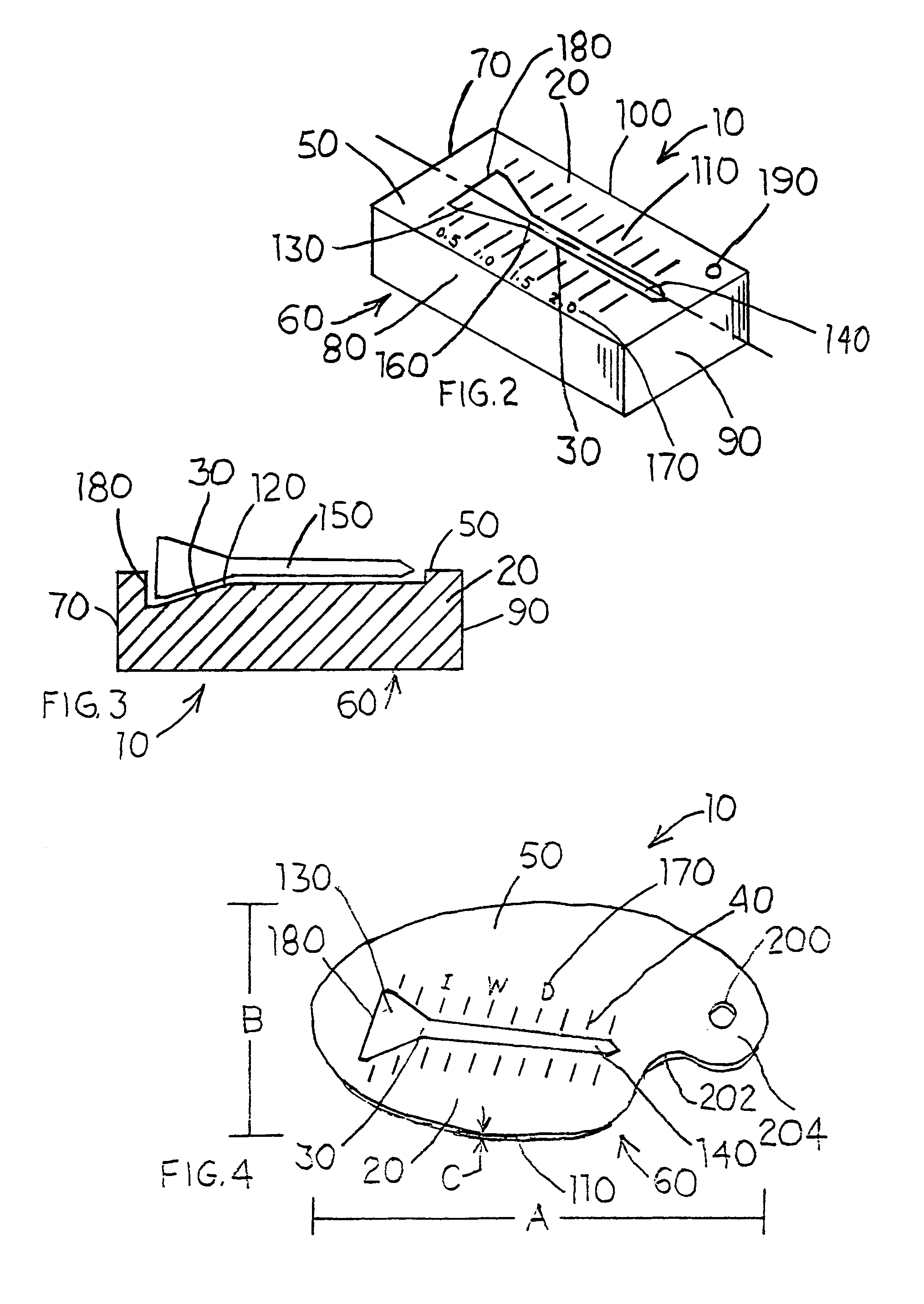
[0015]Referring to FIG. 1, the golf tee marking template 10 comprises a body 20, a receptacle 30 and a plurality of markings 40. In one version, the body will have a top side 50, a bottom side 60, and at least three edges, 70, 80, 90. In another version, the body 20 has four edges 70, 80, 90, 100 thereby forming a square or rectangular body 20.
[0016]In another version, the body 20 is generally circular, oval, elliptical or any other enclosed curvilinear geometric shape as shown in FIG. 4. In the versions in which the body 20 is generally circular, oval, elliptical or curvilinear, the body will have one continuous edge 110 extending around the body 20. A top side 50 and a bottom side 60.
[0017]The body 20 may be manufactured from any rigid or semi-rigid material. In one version, the body 20 comprises plastic. In anot...
PUM
 Abstract
Description
Claims
Application Information