Pillar structure and manufacturing method thereof

a manufacturing method and pillar technology, applied in the field of pillar structure, can solve the problems of long manufacturing time, high manufacturing cost, and inability to make copper pillars with consistent heights with ease, and achieve the effects of reducing manufacturing time, easy control of height of resultant pillar structures, and efficient manufacturing

Active Publication Date: 2017-04-20
UNIMICRON TECH CORP
View PDF13 Cites 0 Cited by
  • Summary
  • Abstract
  • Description
  • Claims
  • Application Information

AI Technical Summary

Benefits of technology

[0004]The disclosure is directed to a pillar structure which can be manufactured efficiently and a manufacturing method of the pillar structure which reduces the manufacturing time; in addition, the height of resultant pillar structures can be easily controlled.
[0017]In view of the above, the metal wire bump and the metal wire are formed on the pad through wire bonding, and the metal plating layer is then formed through plating with use of the pad, the metal wire bump, and the metal wire as the plating seed layer, so as to form the pillar structure. Through applying the manufacturing method of the pillar structure provided herein, the pillar structure made of metal can be formed efficiently, and the height of the resultant pillar structure can be controlled by adjusting the length of the metal wire. Hence, the pillar structure formed by conducting the manufacturing method provided herein can have the consistent height and can be characterized by simple production and low manufacturing costs.

Problems solved by technology

The required height of the copper pillars is about 150 micrometers; during the plating process, it is rather difficult to maintain the consistency of the height of the copper pillars due to manufacturing variations, and thus the copper pillars with the consistent heights cannot be made with ease.
In addition, the copper pillars formed by copper plating requires long manufacturing time and high manufacturing costs, and the copper plating process also causes difficulties in mass production of such copper pillars.

Method used


Image

  • Pillar structure and manufacturing method thereof
  • Pillar structure and manufacturing method thereof
  • Pillar structure and manufacturing method thereof

Examples


Embodiment Construction

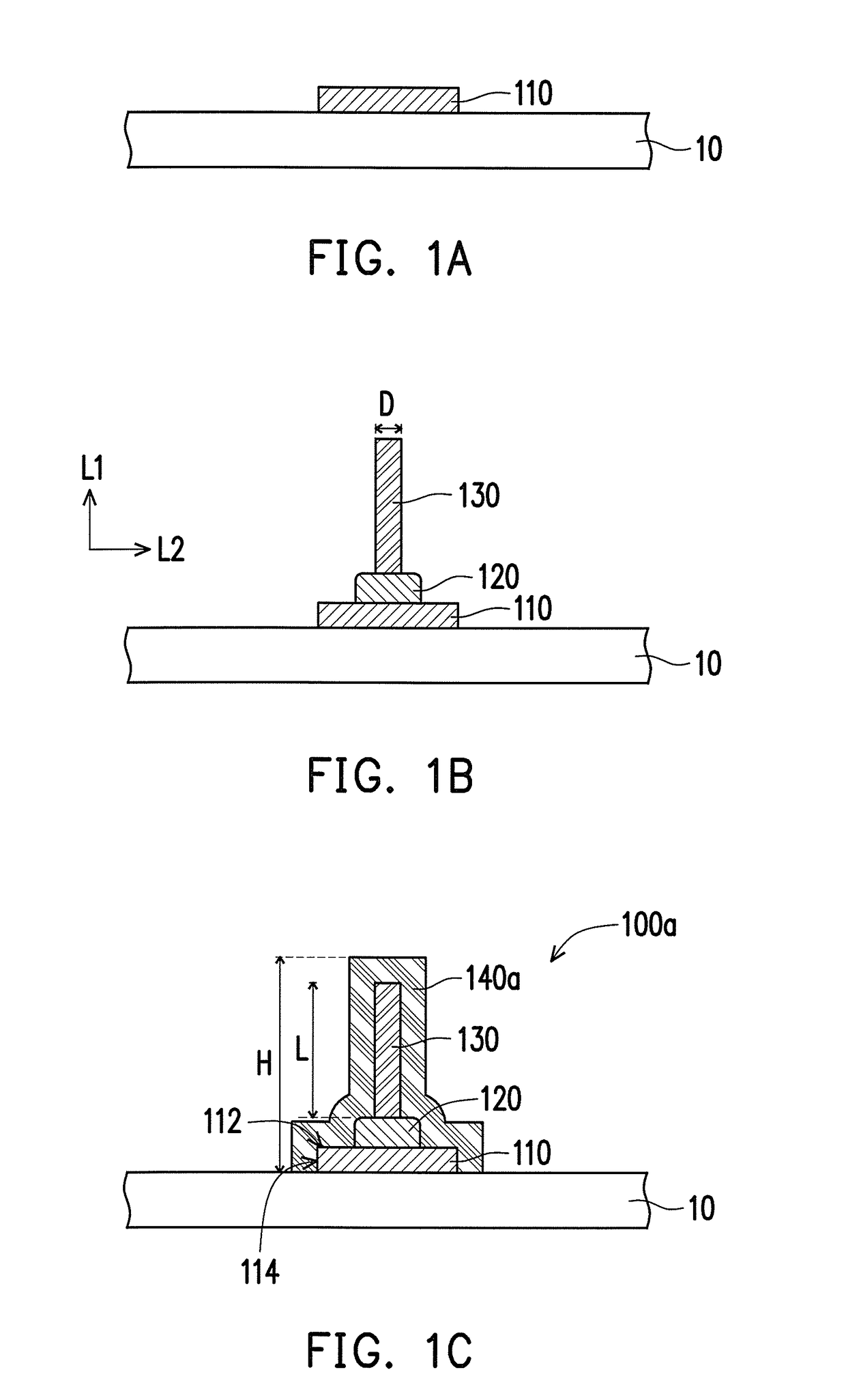
[0022]FIG. 1A to FIG. 1C are schematic cross-sectional diagrams illustrating a manufacturing method of a pillar structure according to an embodiment of the disclosure. With reference to FIG. 1A, in the manufacturing method of the pillar structure provided herein, a pad 110 is formed on a substrate 10. Here, a material of the pad 110 is, for instance, copper, gold, silver, aluminum, nickel, tin, or an alloy of some or all of the above, and the substrate 10 is a circuit board or a package substrate, for instance, which should not be construed as limitations to the disclosure.

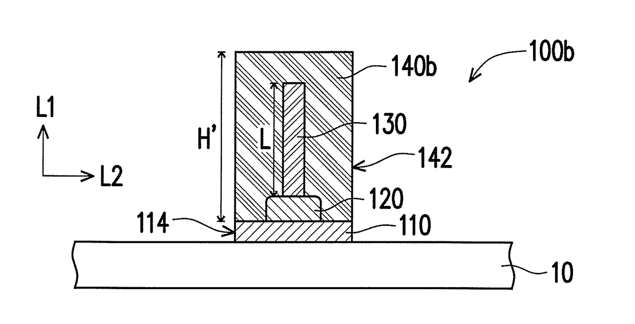
[0023]With reference to FIG. 1B, a wire bonding process is performed to form a metal wire bump 120 and a metal wire 130 on the pad 110. The metal wire bump 120 is formed on the pad 110 through applying a high voltage discharge technique, the metal wire 130 is connected to the metal wire bump 120 and extends in a first extension direction L1, the substrate 10 extends in a second extension direction L2, and the firs...


PUM

PropertyMeasurementUnit
diameteraaaaaaaaaa
heightaaaaaaaaaa
widthaaaaaaaaaa

Abstract

A pillar structure is disposed on a substrate. The pillar structure includes a pad, a metal wire bump, a metal wire, and a metal plating layer. The pad is disposed on the substrate. The metal wire bump is disposed on the pad. The metal wire is connected to the metal wire bump. The metal wire extends in a first extension direction, the substrate extends in a second extension direction, and the first extension direction is perpendicular to the second extension direction. The metal plating layer covers the pad and completely encapsulates the metal wire bump and the metal wire.

Description

CROSS-REFERENCE TO RELATED APPLICATION[0001]This application claims the priority benefit of Taiwan application serial no. 104134172, filed on Oct. 19, 2015. The entirety of the above-mentioned patent application is hereby incorporated by reference herein and made a part of this specification.TECHNICAL FIELD[0002]The disclosure relates to a pillar structure and a manufacturing method thereof. More particularly, the disclosure relates to a pillar structure made of metal and a manufacturing method of the pillar structure.DESCRIPTION OF RELATED ART[0003]In the existing process of circuit boards, plural copper pillars are often made all together through copper plating. The required height of the copper pillars is about 150 micrometers; during the plating process, it is rather difficult to maintain the consistency of the height of the copper pillars due to manufacturing variations, and thus the copper pillars with the consistent heights cannot be made with ease. In addition, the copper pi...

Claims


Application Information

Patent Timeline
Patent Type & Authority Applications(United States)
IPC IPC(8): H01L23/00
CPCH01L24/45H01L24/05H01L24/13H01L24/85H01L2224/8592H01L2224/13026H01L2224/4502H01L2224/13007H01L2224/45015H01L2224/45005H01L2224/1355H05K3/4015H01L2224/1134H01L2224/13562H01L2224/136H05K2201/10287H01L2924/00012H05K1/00
Inventor CHANG, CHENG-JUI
Owner UNIMICRON TECH CORP
Why Eureka
Try Eureka