

Intravenous catheter introducing device
a technology of intravenous catheter and introducing device, which is applied in the direction of catheter, application, diagnostic recording/measuring, etc., to achieve the effect of convenient and safe operation
- Summary
- Abstract
- Description
- Claims
- Application Information
AI Technical Summary
Benefits of technology
Problems solved by technology
Method used
Image

Examples
Embodiment Construction
[0027]Before the present invention is described in greater detail, it should be noted that same reference numerals have been used to denote like elements throughout the specification.
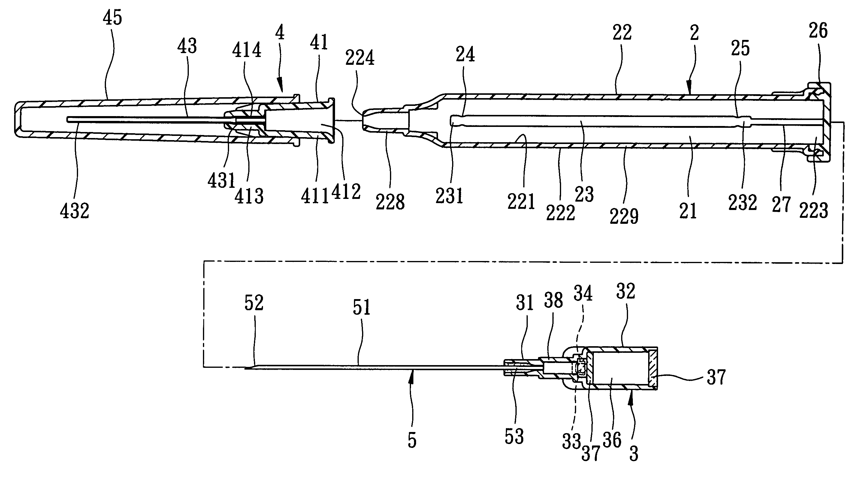
[0028]Referring to FIGS. 3 and 4, the preferred embodiment of an intravenous catheter introducing device according to the present invention is shown to comprise a barrel 2, a needle hub 3, a needle cannula 5, and a catheter connection assembly 4.
[0029]The barrel 2 has front and rear open ends 224,223 opposite to each other in a longitudinal direction, and a surrounding barrel wall 22 which interconnects and which is interposed between the front and rear open ends 224,223. The surrounding barrel wall 22 includes a front smaller-diameter wall portion 228 and a rear larger-diameter wall portion 229 which are opposite to each other in the longitudinal direction and which are proximate to the front and rear open ends 224,223, respectively. The surrounding barrel wall 22 has an inner barrel wall surface 221 w...
PUM
 Abstract
Description
Claims
Application Information