Intravenous catheter introducing device

a technology of intravenous catheters and introducing devices, which is applied in the direction of catheters, hose connections, snap fasteners, etc., can solve the problems of user being exposed to the risk of being pricked by needles, and achieve the effect of convenient operation, simple construction and simple structur

Inactive Publication Date: 2010-03-16
SHUE MING JENG +2
View PDF20 Cites 46 Cited by
  • Summary
  • Abstract
  • Description
  • Claims
  • Application Information

AI Technical Summary

Benefits of technology

[0006]The object of the present invention is to provide an intravenous catheter introducing device which has a simplified construction and which can be operated easily and safely to retract a used needle cannula.

Problems solved by technology

Although a tip protector is provided to be sleeved on the device after use to ensure that the needle is covered, the user is exposed to the risk of being pricked by the needle when sleeving the tip protector on the used device.

Method used


Image

  • Intravenous catheter introducing device
  • Intravenous catheter introducing device
  • Intravenous catheter introducing device

Examples


first embodiment

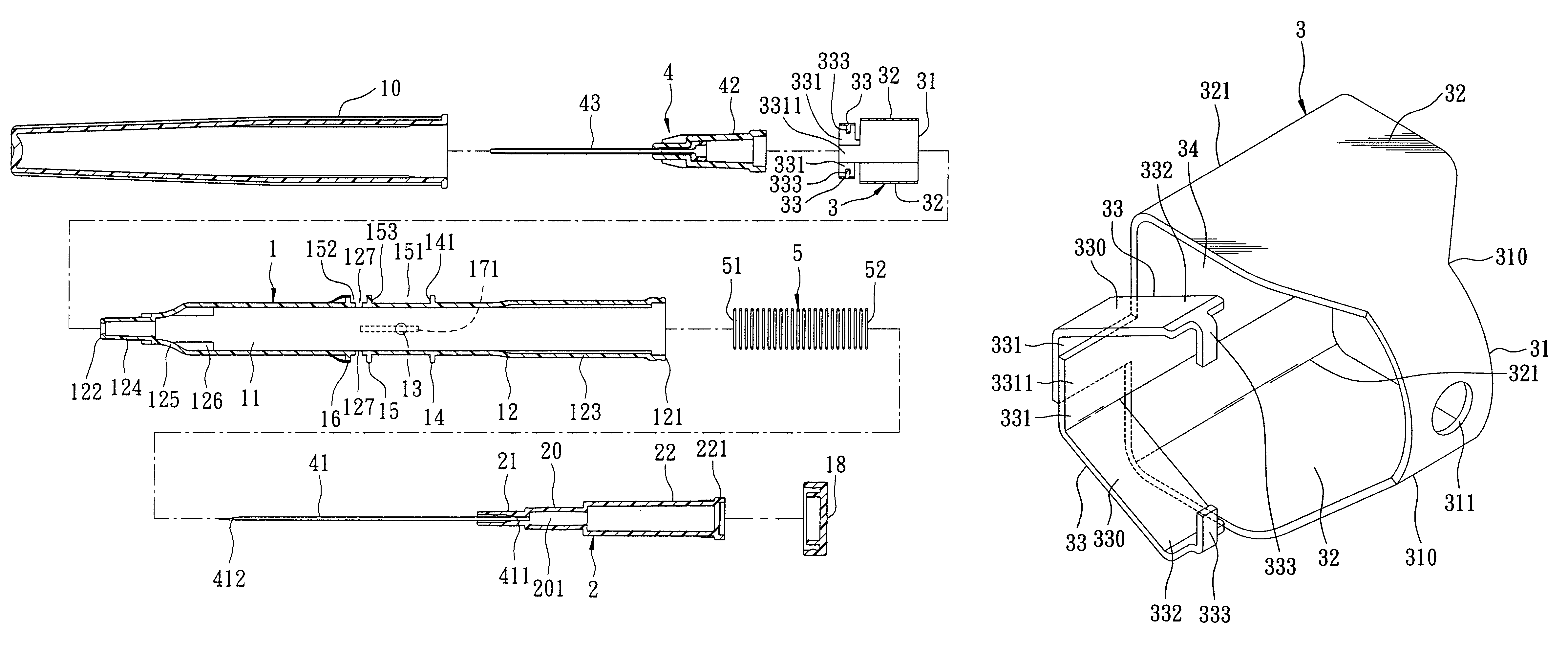
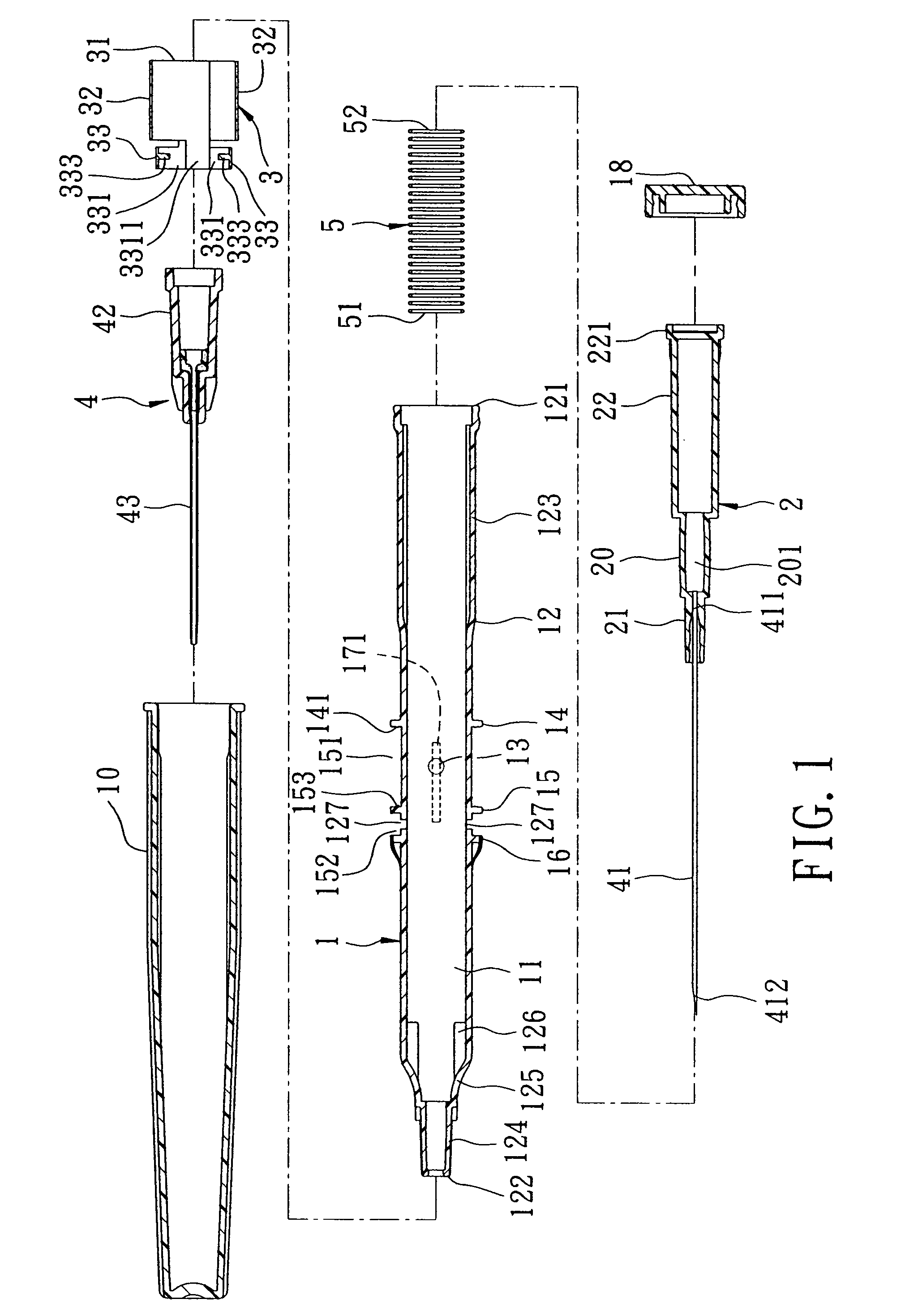
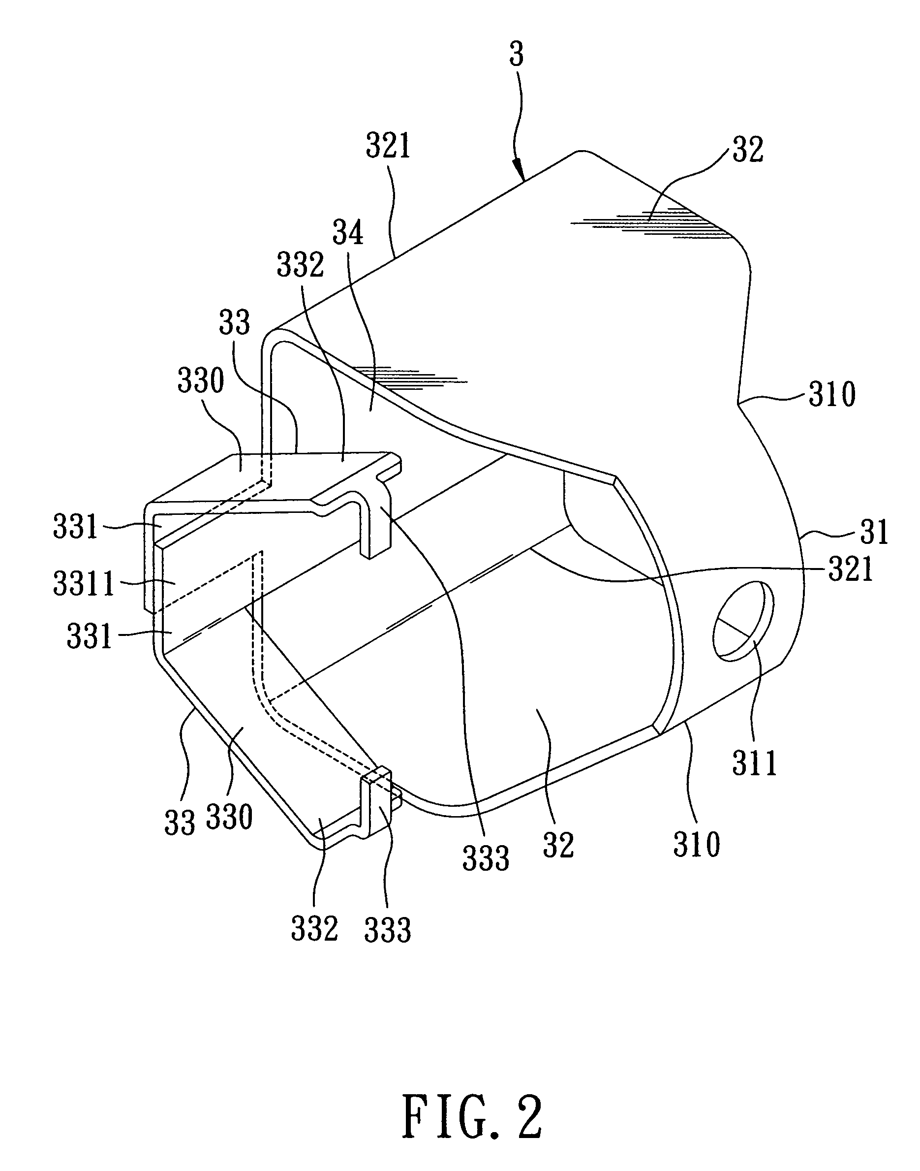
[0042]Referring to FIGS. 8 to 11, the second preferred embodiment of an intravenous catheter introducing device according to this invention is shown to be similar to the first embodiment in construction. The difference resides in that the outer barrel wall surface of the larger-diameter wall portion 123 has an elongated slot 19 which extends through the inner barrel wall surface and which is elongated from an access hole 192 rearwardly to terminate at a restricted hole 191. In addition, the needle hub 2 further includes a retained peg 23 which extends from the rear shell portion 22 and which is configured to extend through the access hole 192 such that the retained peg 23 is guarded by the left and right fingers 333 of the left and right latch members 33 against the biasing action of the biasing member 5 to hold the rear shell portion 22 in the front position. Moreover, when the left and right squeezed wall segments 32 are in the actuated position, i.e., the left and right squeezed ...

second embodiment

[0044]Referring to FIGS. 14 to 18, the third preferred embodiment of an intravenous catheter introducing device according to this invention is shown to be similar to the second embodiment in construction. The difference resides in that the engaging wall segment 31 of the easy release unit 3 is ring-shaped, is sleeved on the outer barrel wall surface of the barrel 1, and has a surrounding edge 312 surrounding the axis. The left and right squeezed wall segments 32 extend from the surrounding edge 312 in the longitudinal direction. The larger-diameter wall portion 123 has a flat guiding surface 172 which extends radially of the outer barrel wall surface so as to guide the movement of the left and right distal segments 332 mounted thereon.

[0045]During operation, the user can hold the barrel 2 with one hand and operate the left and right squeezed wall segments 32 with the same hand to cause the needle hub 2 to move to the rear position for drawing the used needle cannula 41 into the pass...


PUM


Abstract

An intravenous catheter introducing device includes a needle hub slidably inserted into a barrel and holding a needle cannula, a biasing member disposed to bias the needle hub to a rear position so as to retract the needle cannula in the barrel, and an easy release unit including an engaging wall segment which is attached to an outer surface of the barrel, two flexible squeezed wall segments which extend from the engaging wall segment and which is squeezable so as to move two latch members to steer clear of a retained end of the needle hub through an access hole in the barrel, thereby permitting the biasing member to bias the needle hub towards the rear position.

Description

CROSS-REFERENCES TO RELATED APPLICATIONS[0001]This application claims priority to Taiwanese Application No. 095144386, filed Nov. 30, 2006, the disclosure of which is herein incorporated by reference.BACKGROUND OF THE INVENTION[0002]1. Field of the Invention[0003]This invention relates to an intravenous catheter introducing device, more particularly to an intravenous catheter introducing device with a needle cannula which is retractable into a barrel for safe disposal.[0004]2. Description of the Related Art[0005]Conventional medical devices or syringes for medicine injection, drawing blood samples, etc., have to be disposed of safely after use to avoid accidental needle pricks or undesirable contamination. Although a tip protector is provided to be sleeved on the device after use to ensure that the needle is covered, the user is exposed to the risk of being pricked by the needle when sleeving the tip protector on the used device. Therefore, there are available medical devices or syr...

Claims


Application Information

Patent Timeline
Patent Type & Authority Patents(United States)
IPC IPC(8): A61M5/178
CPCA61M25/0606A61M25/0631A61M2005/3228Y10T24/27Y10T24/45628Y10T24/3444Y10T24/44829Y10T24/3439Y10T24/3407
Inventor SHUE, MING-JENGHUANG, DEBORAHSHUE, PHILLIP
Owner SHUE MING JENG
Why Eureka
Try Eureka