
Progressive addition power lens

a technology of addition power and power lens, applied in the field of progressive addition power lens, can solve the problems of blurry object, distortion, blurry object, etc., and achieve the effect of reducing incongruity

Active Publication Date: 2006-05-23
HOYA LENS MFG PHILIPPINES
View PDF14 Cites 4 Cited by
  • Summary
  • Abstract
  • Description
  • Claims
  • Application Information

AI Technical Summary

Benefits of technology

[0025]The invention has as an objective to solve one or more of the above described problems of the conventional near-and-near type progressive addition power lens, including the problems of comfortable use for personal computer work or other desk work, with reduced incongruity. According to one aspect of the invention, there is provided a progressive addition power lens wherein the maximum width, of a clear visual region of a far portion (i.e., a specific view distance correcting portion) which is not important in use, is set so as to be no more than twice as thick as the minimum clear visual region of the intermediate portion and, at the same time, the distance of the intermediate corridor is set to be in the range of 20 to 28 mm, and also the maximum width of a clear visual region of the near portion is set to 30 mm or more. substantially the same height) or above the far point (i.e., at positions higher than the far point, but still at the sides).

Problems solved by technology

It is difficult to clearly distinguish their borders because the progressive addition power lens is continuous from the distant view to the near view and has no border, and is intentionally designed so that a wearer feels as if he is wearing normal correction glasses for ametropia such as farsightedness, nearsightedness, etc.
Furthermore, a distorted aberration is generated, and an object is seen to be blurry and distorted, when moving the head.
In the far and near type lens design, there is a disadvantage in that the clear visual region of the intermediate portion (I) inevitably is narrow.
As a result, in some cases, the dioptric power of the far portion is prescribed to conform to the intermediate length in order to make an intermediate distance appear clear, but because most of the distant view is completely sacrificed, it is impossible to obtain satisfactory vision.
In this type of lens design, however, it is difficult to use the distant dioptric power portion.
However, since the intermediate corridor is so long (in order to obtain a desired near dioptric power), it is impossible to use due to the required extensive eye rotation.
Furthermore, in terms of the size of a frame of glasses currently used, it is impractical for the frame to be filled with only an intermediate portion.
Thus, it is difficult to use.
Because astigmatism and distorted aberration are concentrated on the sides of the intermediate portion having a large size in a frame of glasses, there is a problem of blurring at the sides and large distortion.
Thus, it is difficult to use.
Furthermore, the astigmatism occurs in the side direction of the near portion, and thus a wearer has a limited side direction visual field, and a sense of incongruity.

Method used


Image

  • Progressive addition power lens
  • Progressive addition power lens
  • Progressive addition power lens

Examples


Embodiment Construction

[0033]The present invention will now be described in detail by describing illustrative, non-limiting embodiments thereof with reference to the accompanying drawings.

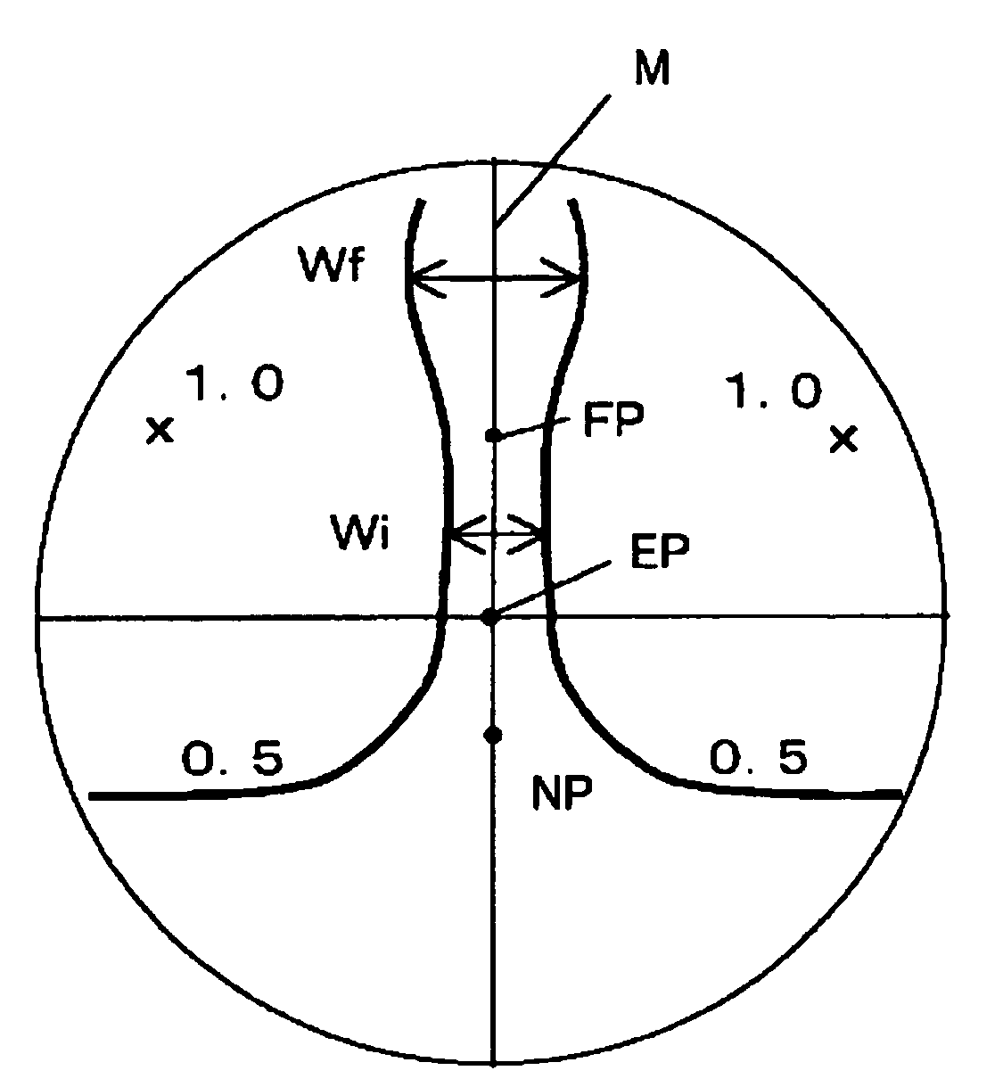
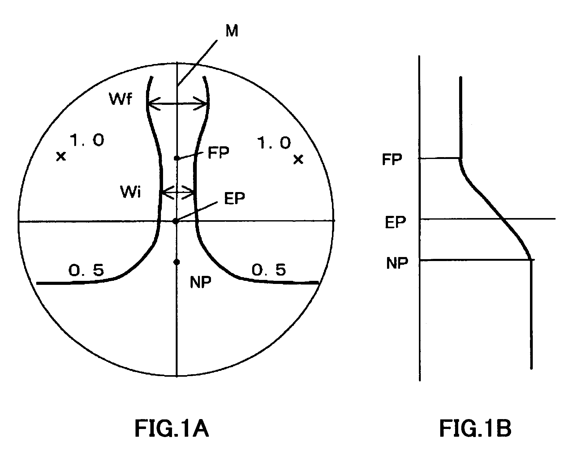
[0034]FIG. 1 shows an illustrative, non-limiting embodiment of the present invention. That is, FIG. 1A shows an aberration distribution and FIG. 1B shows a dioptric power variation on the principal meridian curve. In this embodiment, the decrease in refractive power in the range from the near point (NP) to the far point (FP) is 1.5 D.

[0035]Furthermore, the length of the intermediate corridor (length of NP−FP) is 25 mm. The maximum width (Wf) of the clear visual region of the far portion is not more than twice the minimum width (Wi) of the clear visual region of the intermediate portion (Wf is 14 mm and Wi is 7.5 mm in this specific embodiment). The clear visual region of the near portion is more than 60 mm wide, and extends to the left and right ends of the lens. The maximum astigmatism of the side portions is 1.0 D, and...


PUM


Abstract

A progressive addition power lens with a length of the intermediate corridor in the range of 22 to 28 mm, and a clear visual region, which is defined as a region where astigmatism is 0.5 diopters or less, has a horizontally maximum width thereof in the distant dioptric power region, which is twice as thick as or less than a horizontally minimum width in the intermediate corridor. Furthermore, the clear visual region defined as a region where astigmatism is 0.5 diopters or less has a width of 30 mm or more horizontally in the near dioptric power region. In addition, a position, where astigmatism distributed at the sides of the lens has the maximum value, is located in an almost horizontal direction with a far point positioned above the intermediate corridor or is located above the far point.

Description

BACKGROUND OF THE INVENTION[0001]1. Field of the Invention[0002]The present invention is related to a progressive addition power lens which is used for close-range work such as personal computer work, bookkeeping, reading, etc., and is mainly used for patients having poor focusing ability due to presbyopia.[0003]2. Description of the Related Art[0004]First, a general structure of a progressive addition power lens will be described. FIG. 5 is a view showing the general structure of a progressive addition power lens. FIG. 5A shows the entire structure thereof and FIG. 5B shows the variation in refractive power on the principal meridian curve. The progressive addition power lens has an aspheric shape, which is called a progressive refractive power surface (hereinafter, referred to as a progressive surface), on any one of a pair of refractive surfaces forming a lens (conventionally, the eye side is called an inner surface and the opposite side thereof is called an outer surface).[0005]T...

Claims


Application Information

Patent Timeline
Patent Type & Authority Patents(United States)
IPC IPC(8): G02C7/06G02C7/02
CPCG02C7/066G02C7/061
Inventor SHINOHARA, TOSHIHIDEKAGA, TADASHI
Owner HOYA LENS MFG PHILIPPINES
Learn More