Light tube and power supply circuit

a technology of power supply circuit and light tube, which is applied in the field of light tube, can solve the problems of short life expectancy of conventional fluorescent light tube, high power consumption, and prone to failur

Inactive Publication Date: 2006-05-23
ILUMISYS
View PDF23 Cites 362 Cited by
  • Summary
  • Abstract
  • Description
  • Claims
  • Application Information

AI Technical Summary

Problems solved by technology

Conventional fluorescent light tubes have a short life expectancy, are prone to fail when subjected to excessive vibration, consume high amounts of power, require a high operating voltage, and include several electrical connections which reduce reliability.
Conventional ballasts are highly prone to fail when subjected to excessive vibration.

Method used


Image

  • Light tube and power supply circuit
  • Light tube and power supply circuit
  • Light tube and power supply circuit

Examples


Embodiment Construction

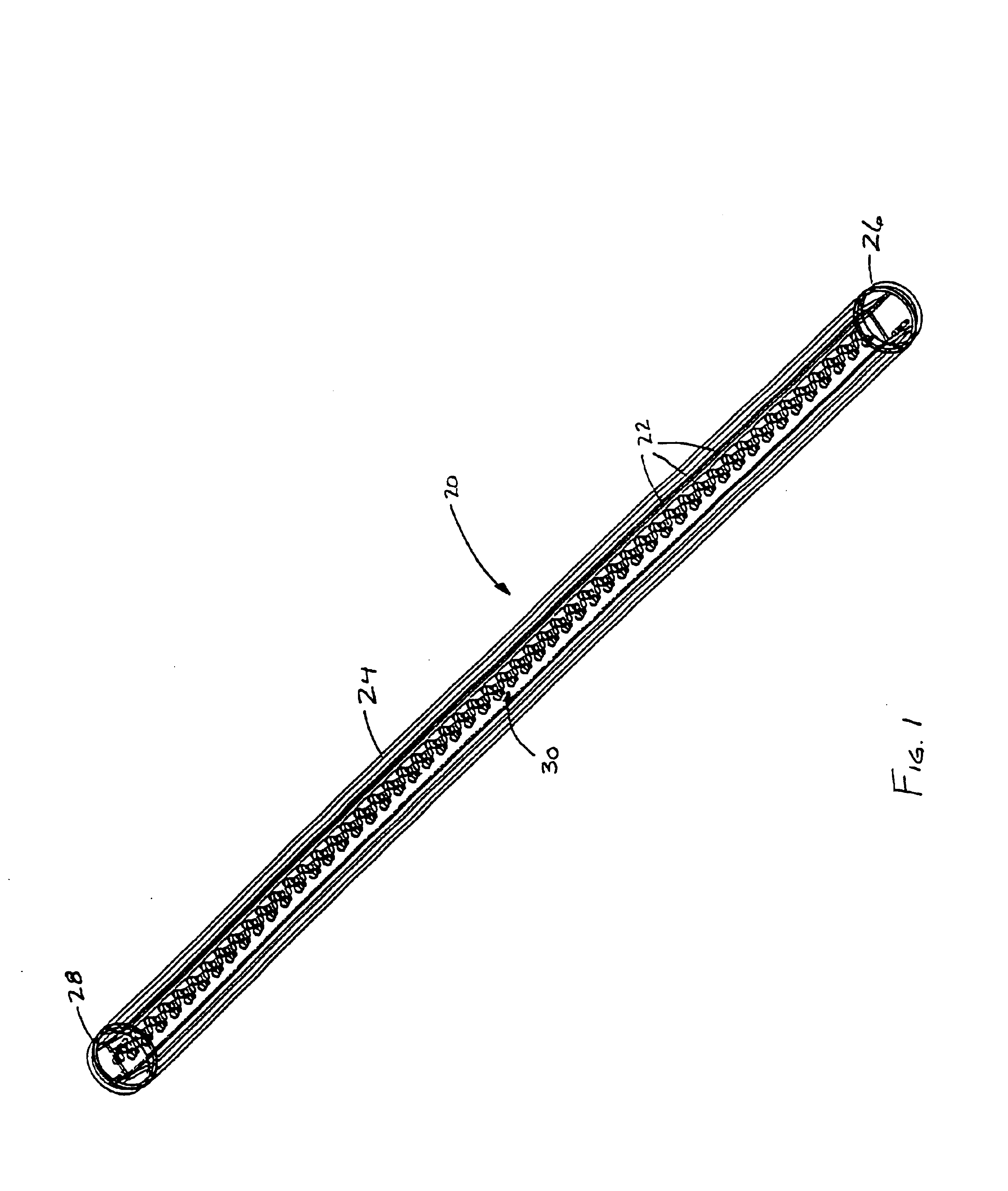
[0016]FIG. 1 is a line drawing showing a light tube 20 in perspective view. In accordance with the present invention, the light tube 20 is illuminated by LEDs 22 packaged inside the light tube 20. The light tube 20 includes a cylindrically shaped bulb portion 24 having a pair of end caps 26 and 28 disposed at opposite ends of the bulb portion. Preferably, the bulb portion 24 is made from a transparent or translucent material such as glass, plastic, or the like. As such, the bulb material may be either clear or frosted.

[0017]In a preferred embodiment of the present invention, the light tube 20 has the same dimensions and end caps 26 and 28 (e.g. electrical male bi-pin connectors, type G13) as a conventional fluorescent light tube. As such, the present invention can be mounted in a conventional fluorescent light tube socket (not shown).

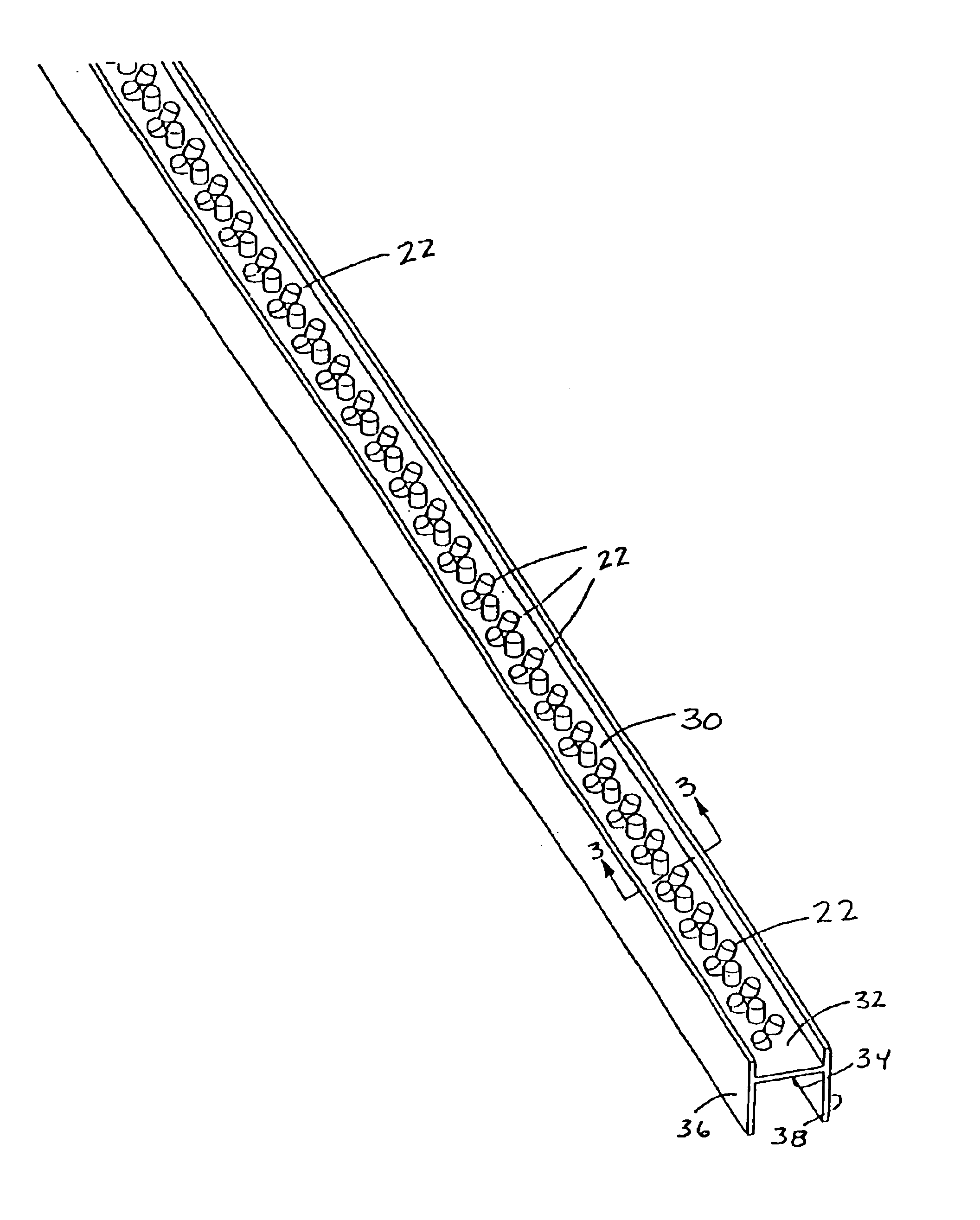
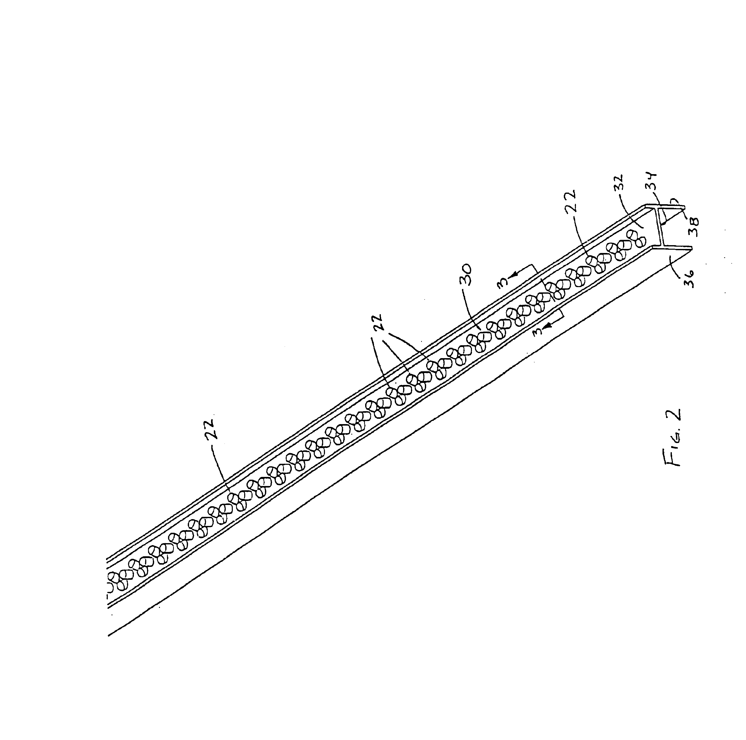
[0018]The line drawing of FIG. 1 also reveals the internal components of the light tube 20. The light tube 20 further includes a circuit board 30 with ...


PUM


Abstract

The present invention provides a light tube for illumination by a power supply circuit including a bulb portion and a pair of end caps disposed at opposite ends of the bulb portion. A plurality of light emitting diodes are disposed inside the bulb portion and in electrical communication with the pair of end caps for illuminating in response to electrical current to be received from the power supply circuit.

Description

CROSS-REFERENCE TO RELATED APPLICATIONS[0001]This application claims the benefit of U.S. Provisional Application Ser. No. 60 / 181,744 filed Feb. 11, 2000.FIELD OF THE INVENTION[0002]The present invention relates to a light tube illuminated by LEDs (light emitting diodes) which are packaged inside the light tube and powered by a power supply circuit.BACKGROUND OF THE INVENTION[0003]Conventional fluorescent lighting systems include fluorescent light tubes and ballasts. Such lighting systems are used in a variety of locations, such as buildings and transit buses, for a variety of lighting purposes, such as area lighting or backlighting. Although conventional fluorescent lighting systems have some advantages over known lighting options, such as incandescent lighting systems, conventional fluorescent light tubes and ballasts have several shortcomings. Conventional fluorescent light tubes have a short life expectancy, are prone to fail when subjected to excessive vibration, consume high am...

Claims


Application Information

Patent Timeline
Patent Type & Authority Patents(United States)
IPC IPC(8): H05B37/02H01L25/13H05B44/00
CPCF21K9/17H05B33/0803F21K9/175F21V23/00H05B37/02H05B33/0815F21V19/008F21Y2101/02H01L25/13Y02B20/386F21Y2103/003H01L2924/0002F21Y2103/10F21Y2115/10F21K9/60F21K9/278Y02B20/30H05B47/10H05B45/3578H05B45/3725H05B45/10H05B45/325H01L2924/00H05B45/14F21V23/009F21K9/272F21K9/275B60Q3/80F21V19/003F21V23/023F21V3/02F21V15/015F21V23/06F21S4/28F21K9/90F21K9/66F21V23/02
Inventor TIMMERMANS, JOSRAYMOND, JEAN C.
Owner ILUMISYS
Why Eureka
Try Eureka